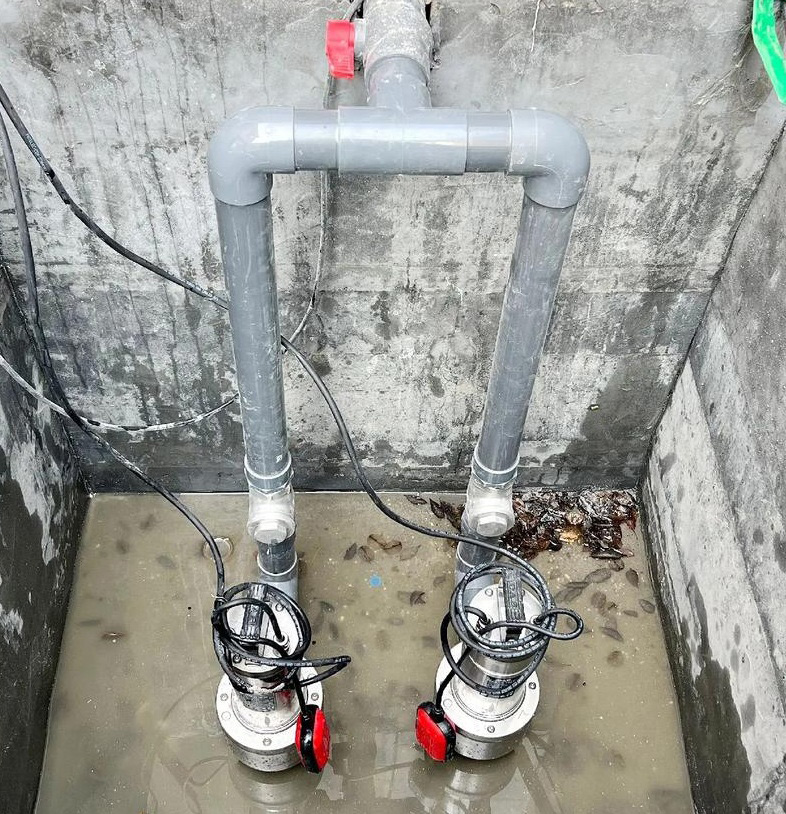
Seal-free self-priming pumps are primarily used for low-level lifting in the wastewater treatment system of the Second Purification Plant, replacing submersible sewage pumps and long-shaft submerged lift pumps in suction tanks. In summary, the use of seal-free self-priming pumps offers simple operation and reduced maintenance workload, making them highly suitable for the wastewater treatment system in natural gas purification plants where safety requirements are critical. Anhui Shengshi Datang now provides an analysis and summary of the usage of seal-free self-priming pumps.
1. Structure and Working Principle of Seal-Free Self-Priming Pumps
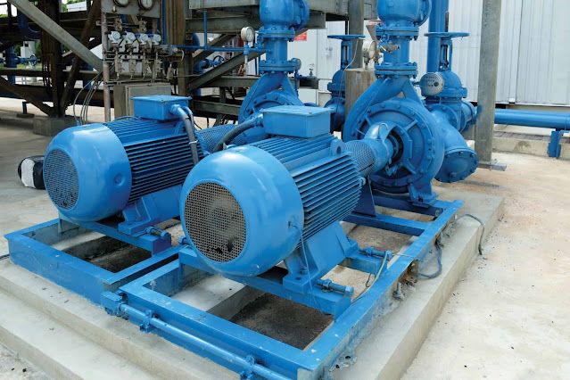
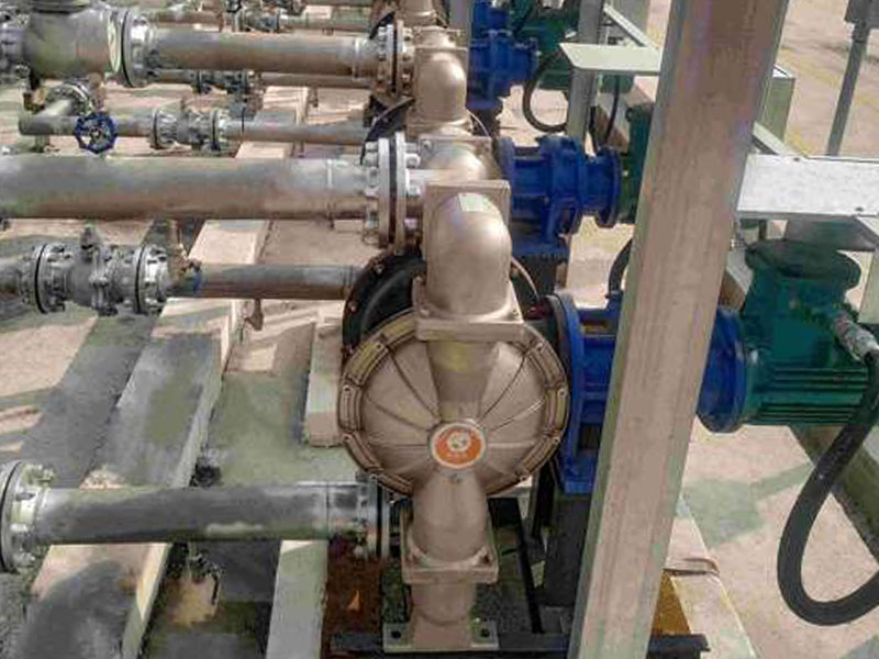
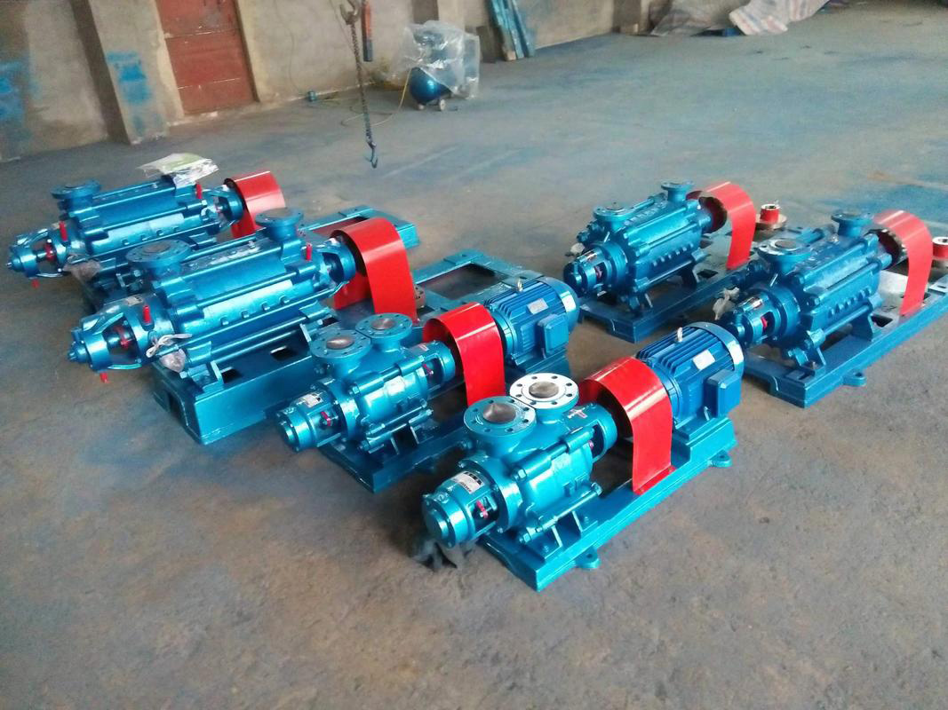
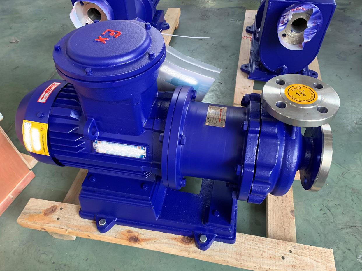
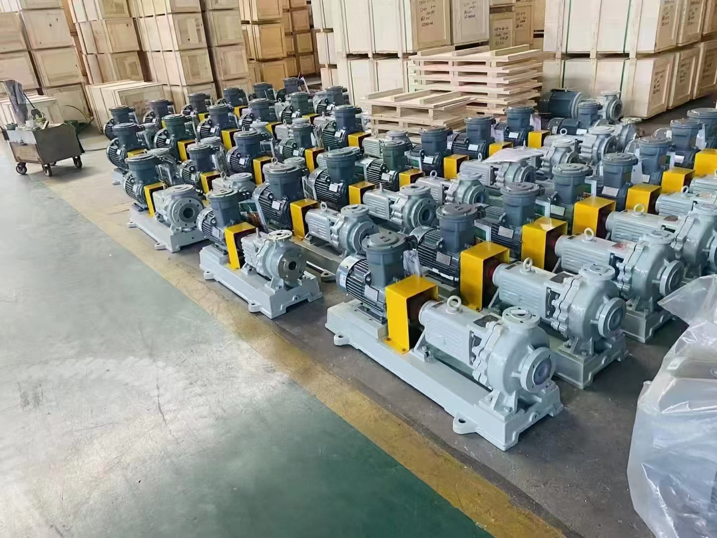
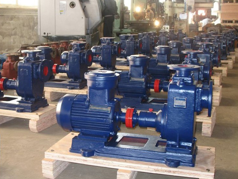
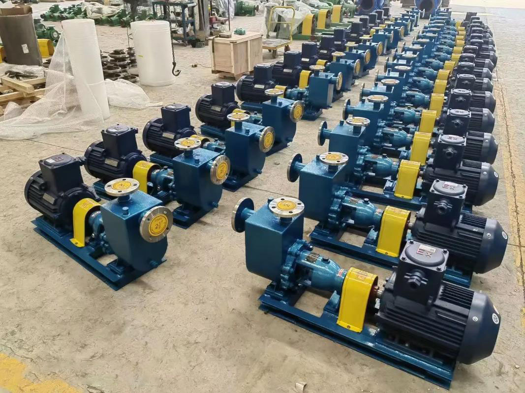
(1) Basic Structure of Self-Priming Pumps
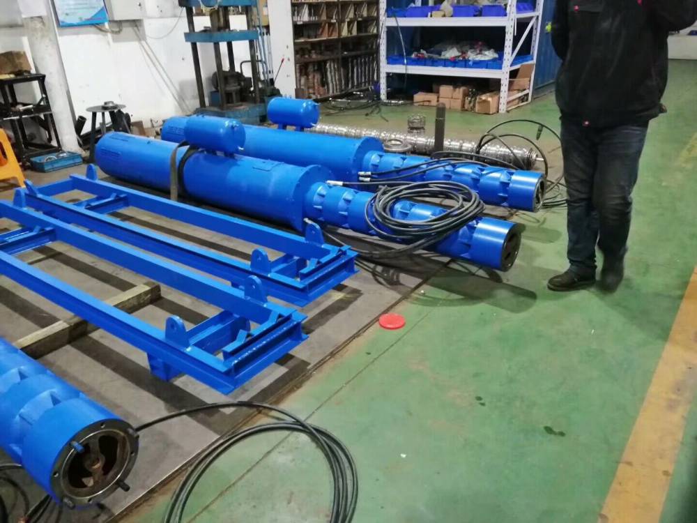
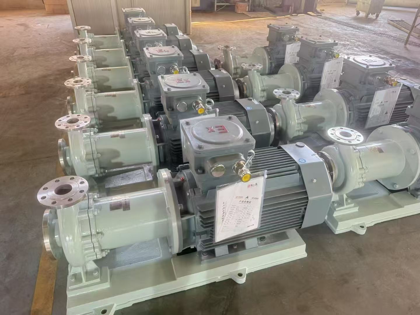
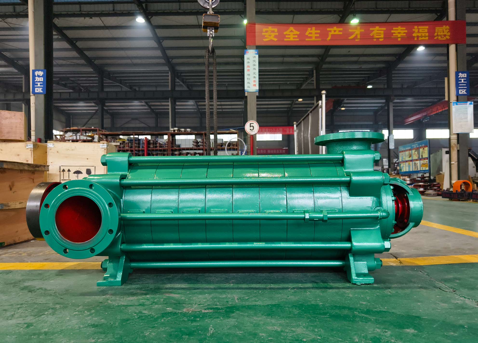
Typically, the basic structure of a self-priming pump mainly includes the following components: a liquid storage chamber, a pump body rotor, inlet and outlet valves, a motor, and several other parts that together form the pump.
(2) Basic Working Principle of Seal-Free Self-Priming Pumps
The working principle primarily involves the following processes: first, self-priming and exhaust; second, normal pumping of liquid.
2. Analysis of the Practical Usage of Seal-Free Self-Priming Pumps
(1) Advantages of Seal-Free Self-Priming Pumps in Low-Level Liquid Transport
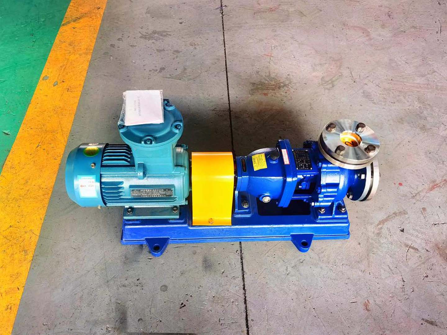
① Small seal-free self-priming pumps do not require specialized installation foundations or anchor bolts. They can be placed horizontally, making installation simple. They can easily replace existing lift pumps or submersible pumps.
② Easy operation. Normal operation only requires priming the pump once, after which starting and stopping can be done effortlessly.
③ Strong self-priming capability. Within the suction range, they can replace submersible electric pumps, reducing safety hazards.
④ No sealing required. Completely eliminates leakage, dripping, and seepage. During operation, the sealing device does not experience friction, extending its lifespan by more than 10 times. The self-priming performance is stable and reliable, requiring only one initial priming for lifelong self-priming, with superior self-control capability.
⑤ No need for a separate suction device, resulting in a simpler structure and safer operation.
⑥ Maintenance of seal-free self-priming pumps is convenient. These devices rarely malfunction, are easier to maintain compared to other equipment, and do not require significant financial investment.
(2) Specific Analysis of the Technical Performance of Seal-Free Self-Priming Pumps
① Due to the simple structure of self-priming pumps and the use of dynamic combined airflow sealing, the pump's operation does not affect the sealing device. Compared to long bearings, this device is easier to operate and has a lower probability of issues.
② The device primarily relies on the principle of air-water separation, giving it strong self-priming performance. Especially after using an "air control valve," the siphon phenomenon can be maximally disrupted, achieving the effect of lifelong self-priming.
③ The drawback is that it does not have a high work efficiency and consumes more energy.
④ After starting the self-priming pump, it takes some time before water is discharged. Therefore, designers of pump stations must pay attention to this situation, meaning multiple backup pumps should be prepared.
⑤ When a self-priming pump is used to lift wastewater, certain parameters such as flow rate, head, and suction head must be kept within allowable limits. Otherwise, equipment malfunctions may occur, adversely affecting the pump's smooth operation.
⑥ Based on the basic principle of self-priming pumps, it is essential to ensure that the connections at the water pipe interfaces are properly sealed. If the pump experiences insufficient flow, it may fail to operate smoothly.
3. Technological Innovations
(1) Installation of an Air Valve in the Suction Pipeline to Disrupt the Siphon Phenomenon and Retain Sufficient "Priming Liquid" in the Pump Cavity
① In the early stages of using seal-free self-priming pumps, the electric air valves designed by manufacturers were not installed, mainly because they were unsuitable for flammable and explosive environments. Additionally, air valves of this model had many defects, such as frequent malfunctions. Therefore, personnel should use solenoid valves as air valves based on actual application conditions, significantly improving durability and stability.
② Function and Principle of the Electric Air Control Valve
The air valve is typically installed at the high point of the self-priming pump's suction pipe. When the pump starts, the solenoid valve is energized, and the valve core seats downward, ensuring the suction pipeline is sealed to achieve self-priming. When the pump stops, the air valve opens, allowing air to enter the pipe cavity. This separates the liquid in the suction pipe and pump cavity, preventing backflow of the liquid in the pump cavity. This completely disrupts the siphon phenomenon, ensuring the self-priming pump operates normally during the next self-priming cycle. The air valve is particularly suitable for self-priming pumps that start and stop frequently, reducing the need for priming operations.
(2) Use of Steel Wire Flexible Hoses in the Suction Pipe to Facilitate Daily Maintenance and Troubleshooting of Self-Priming Pumps
① Typically, self-priming pumps in wastewater systems, like other pumps, require regular cleaning at specific intervals. If the suction tank is deep, maintaining metal suction pipes requires collaboration among several personnel.
② If the suction pipe of the self-priming pump operates under negative pressure, such as when pinholes occur, insufficient air may reach the pump, preventing normal operation. Moreover, such issues are not easily detectable. By using steel wire flexible hoses, if leakage points occur, the hose can be pulled back to the ground for inspection promptly.
(3) Adjusting the Pump Outlet Diameter to Prevent Motor Overload
① From the perspective of seal-free self-priming pumps, some manufacturers fail to achieve precision during production, resulting in inconsistent power output between the motor and the pump body. This can easily lead to overload situations.
② During specific applications, personnel need to adjust the flow path based on the actual degree of overload to ensure the pump's flow rate remains within allowable limits.