China bin activator manufacturer specializing bulk materials handling

In every aspect of industrial production, the handling of bulk materials is always a crucial task. Whether it is the food, chemical, construction, or mining industries, they all depend on the efficient handling of various bulk materials. However, in reality, the process of handling bulk materials often encounters numerous problems, which seriously affect the smooth progress of production. In storage and transportation equipment such as silos and pipelines, materials are prone to blockage due to factors such as moisture absorption, friction between particles, and unreasonable design. This not only results in the materials being unable to flow smoothly but may even come to a complete standstill, forcing the production line to be interrupted. 

China bin activator


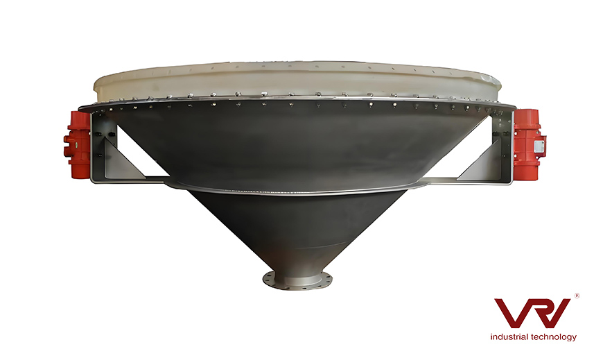
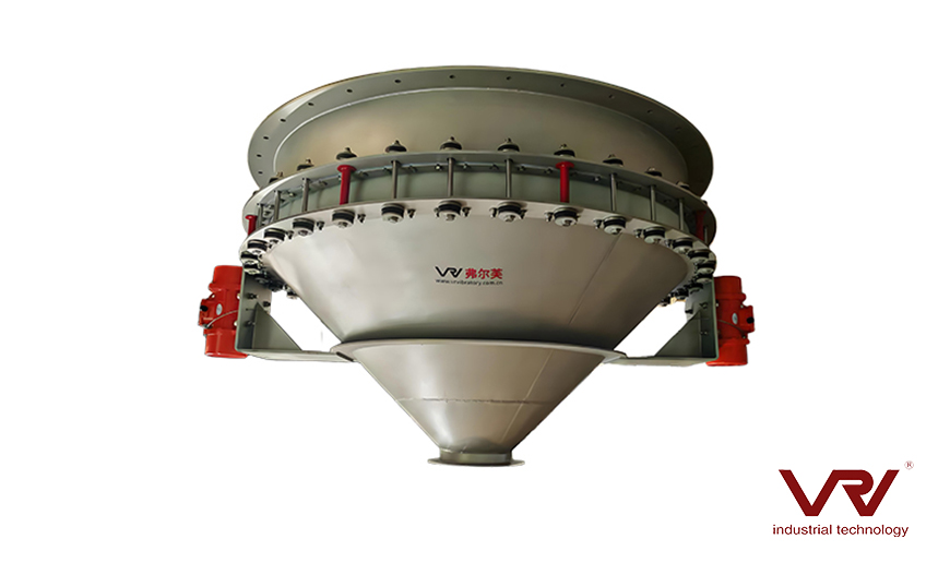
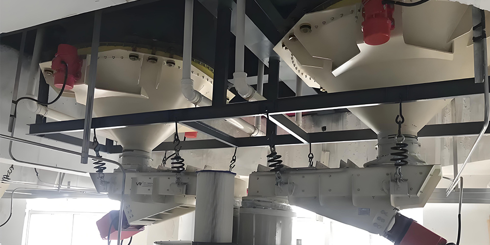
Bin Activator, also known as vibrating bottom, is a key device specifically designed to solve the flow problems during the storage and transportation of bulk materials. Simply put, it is usually installed at the discharge outlet or the bottom of the silo. Through the vibration generated by the internal vibrating motor, it transfers energy to the materials, making the materials that are prone to stagnation and blockage become active again and flow smoothly.

Silo bin activator

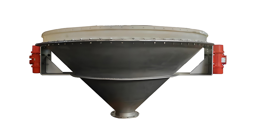
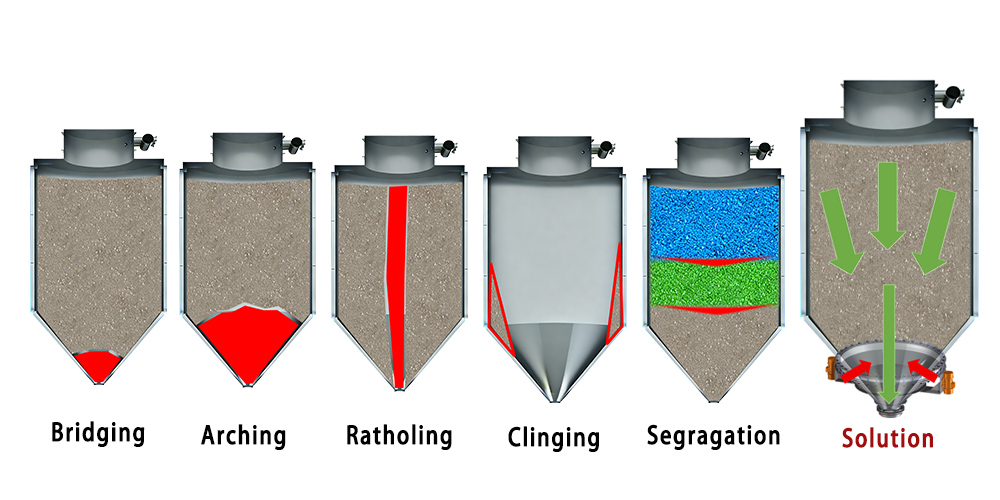
Specifically, a Bin Activator generally consists of a vibrating motor and a conical device. The vibrating motor can adjust the frequency, amplitude, and direction of vibration precisely to adapt to the characteristics and flow requirements of different materials. When the vibration is generated, the materials are subjected to periodic forces, and the friction and adhesion between particles are weakened. Thus, blockage structures such as arches and rat holes that may have formed are broken, enabling the materials to flow out of the silo in a uniform and stable manner.


Applications of Bin Activator in Multiple Industries:

1. Preventing Material Blockages:

    - In the food industry, powdery materials such as flour and sugar powder are prone to caking due to moisture absorption, which can lead to silo blockages. The continuous vibration of the Floor Bin Activator effectively prevents material caking, ensuring that the materials flow smoothly into the production process and guaranteeing the continuous operation of the food production line.

    - In the chemical industry, when dealing with sticky materials, the Bin Activator also performs outstandingly. For example, some resin raw materials are extremely likely to adhere to the silo wall during conventional storage and transportation, causing blockages. The vibrating action of the Bin Activator can keep the materials in relative motion with the silo wall, avoiding adhesion and maintaining the normal flow of the materials.

Silo bin activator

2. Promoting Uniform and Stable Material Flow:

    - In the building materials industry, the uniform transportation of materials such as sand, gravel, and cement is crucial for the quality of concrete. The Bin Activator can make these materials flow out of the silo at a stable flow rate, ensuring the accurate proportioning of various components during the concrete mixing process, thereby improving the quality stability of concrete.

    - In the mining field, during the transportation and processing of ores, the Bin Activator can ensure that ores of different particle sizes are evenly mixed and flow out, providing a stable raw material supply for subsequent beneficiation, smelting and other processes, and improving production efficiency and product quality.

Silo bin activator

VRV China bin activator manufacturer would provide you excellent quality products with competitive price.

1. Profound Technological Foundation

Chinese VRV manufacturers have always maintained high investment in technological research and development.

2. Abundant Industry Experience

Thanks to years of market cultivation, Chinese VRV manufacturers have accumulated rich industry experience and served numerous customers in different industries. Our customers are from many countries in Asia and Europe, engaging in industries such as lithium batteries, food, and building materials.

3. High-quality Product Quality

Chinese VRV manufacturers attach great importance to product quality and strictly control every aspect, from raw material procurement, production processes to quality inspection.

4. Complete After-sales Service

To relieve customers of any concerns, Chinese VRV manufacturers provide all-round high-quality after-sales services. We offer a one-year warranty period, 24-hour online problem-solving and on-site repair services.

5. Customer Testimonials and Success Stories

Numerous enterprises have achieved remarkable efficiency improvements after adopting the Bin Activator and VRV systems provided by Chinese manufacturers. Their personal experiences are strong evidence of the excellent performance of the products.

China bin activator manufacturer


Electromagnetic vibrator manufacturer in China specializing in bulk materials non-damaging handling

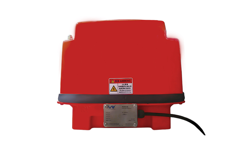
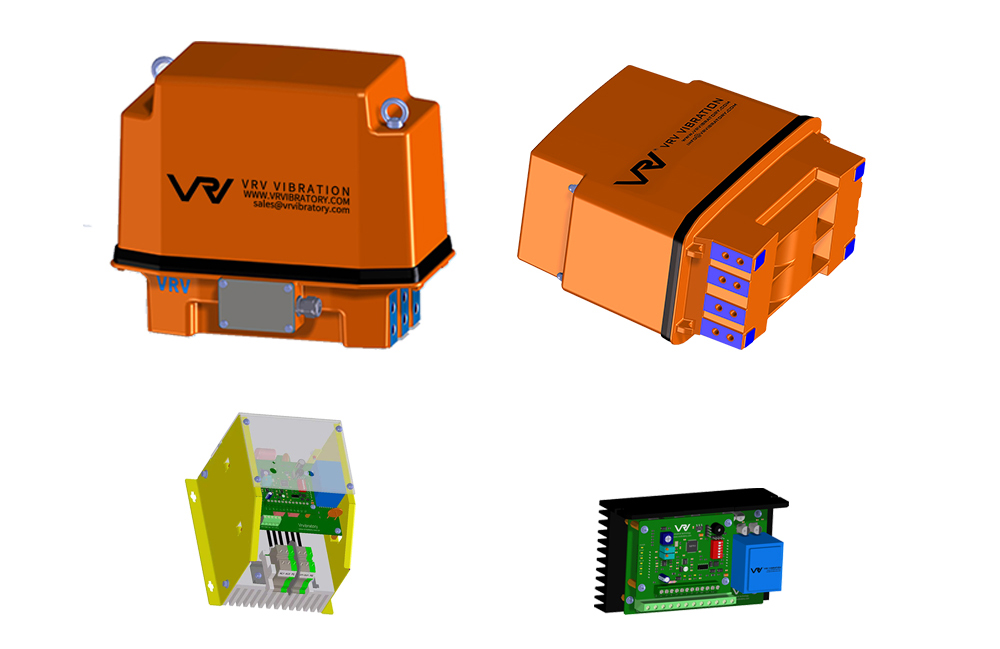
An electromagnetic vibrator is a device that directly converts electrical energy into mechanical motion based on the principle of electromagnetic induction. Due to its simple structure and the fact that the generated vibration force is in a linear motion, it is also known as a linear vibrator. The electromagnetic vibrator does not require an intermediate transmission mechanism. It has direct energy conversion, fast response speed and high control precision. Electromagnetic vibrating feeders and electromagnetic vibrating screens have been widely used in the fields of bulk material conveying and screening.

Electromagnetic vibrator


VRV as a leading electromagnetic vibrator manufacturer in China, can provide you high-quality electromagnetic vibrators with more competitive price. VRV has electromagnetic vibrators of various models, which can meet the usage needs of different customers. There are mainly the compact BM electromagnetic vibrators and the large-sized EV electromagnetic vibrators.

Electromagnetic vibratorElectromagnetic vibrator

Different from the general-purpose electromagnetic vibrators on the market that compromise on performance and have insufficient durability, VRV's products are specifically designed for harsh industrial environments. The following advantages make us stand out: 

1. Extreme precision and stable performance Relying on advanced electromagnetic resonance technology, VRV's electromagnetic vibrators can provide a stable and adjustable vibration frequency (33Hz - 50Hz - 60Hz, customization supported) and exciting force range, perfectly adapting to diverse needs - from gentle feeding in pharmaceutical production lines to high-intensity compaction in concrete construction, they can handle it precisely. Each device undergoes more than 100 hours of dynamic testing before shipment to ensure zero performance fluctuations, reducing product losses and production downtime by up to 30%. 

2. Exceptional durability VRV adheres to the use of high-quality raw materials: for the food and chemical industries, a corrosion-resistant 304 stainless steel shell is used; to achieve lightweight portability, a reinforced aluminum alloy core is selected; the coil uses military-grade copper wire with excellent heat resistance. The product's protection level reaches IP67 (dust and waterproof), and its service life exceeds 8,000 hours, twice the industry average. There is no need for frequent replacement. 

3. High energy efficiency and cost reduction With the continuous increase in energy costs, VRV's electromagnetic vibrators feature high energy conversion efficiency as the core design highlight. While ensuring high quality, the price is also more competitive. 

4. Customization for the entire industry, with seamless solution adaptation VRV's R & D team will communicate and collaborate with customers. Combining specific application scenarios, space limitations, and performance requirements, they will design the vibrators tailored to the needs.

Electromagnetic vibrator manufacturer


Enclosed electromagnetic vibrating feeders with support in glass industry

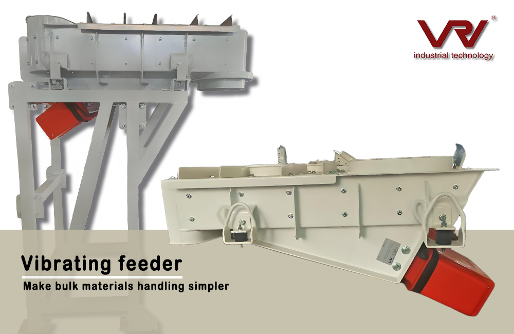
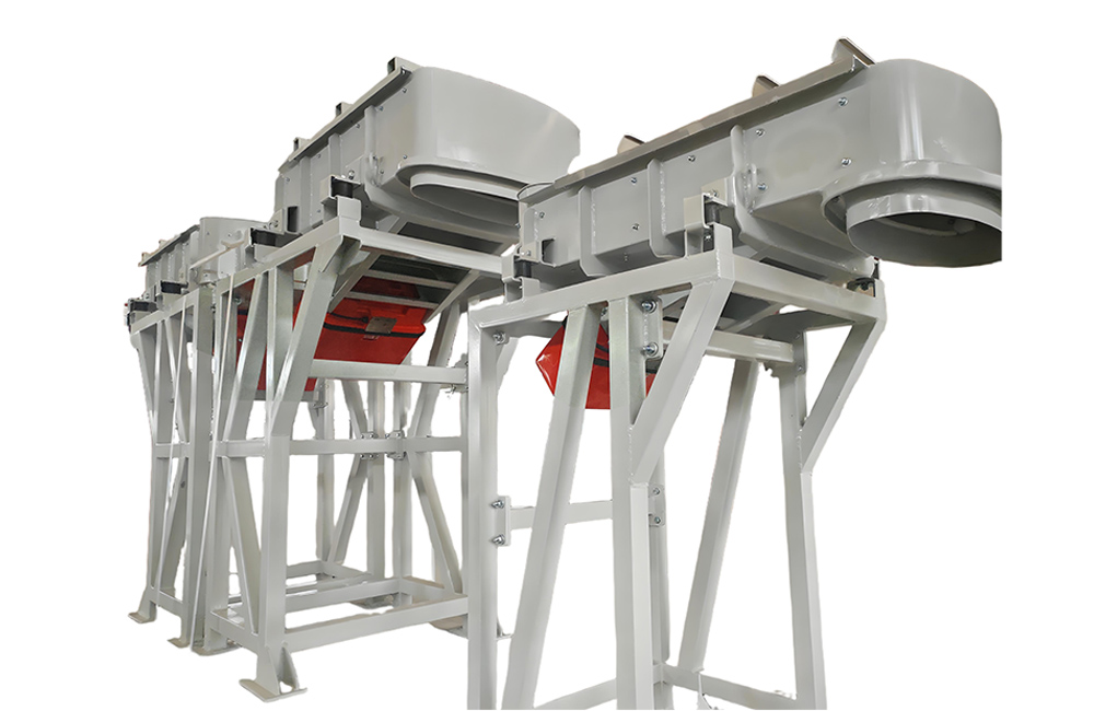
The vibrating feeder is a device that realizes material conveying and feeding by using the principle of vibration. It is widely used in industries such as mining, metallurgy, building materials, chemical industry, and food. The vibrating feeder is mainly used to convey lumpy, granular or powdery materials evenly and continuously from storage bins or other material sources to subsequent equipment (such as crushers, screeners, conveyors, etc.). At the same time, it can also be used for rough screening of materials.

Vibrating feeders


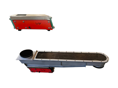
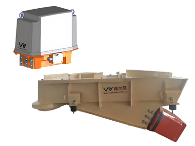
VRV vibrating feeders features a sturdy structure and flexible design, capable of meeting diverse requirements. This is a large-sized electromagnetic vibrating feeder, driven by an electromagnetic vibrator. It adopts a closed structure, providing higher sealing performance, and is applied in the glass industry.

Materials

SiO₂, Na₂CO₃, CaCO₃

Capacity

0-200 tph

Drive

EV300 (VRV electromagnetic vibrator)

Body material

Carbon steel

Conveying distance

1.5-2.5m

The enclosed electromagnetic vibrating feeder can flexibly adjust the material flow rate through the controller. The CV15 and CV25 series controllers of VRV support 4 - 20mA analog control and can be connected to the PLC for remote operation, enabling stepless speed regulation of the feeder from 0 to 100%.

Electromagnetic vibrating feeders

1. Uniform and stable feeding

The directional vibration generated by a vibrating motor or an electromagnetic vibrator can convey materials continuously and evenly along a predetermined trajectory, avoiding material accumulation or feed interruption, ensuring the stable operation of subsequent equipment (such as crushers and screeners), and improving the overall production efficiency.

Electromagnetic vibrators

2. Flexible and convenient adjustment

The feeding amount can be easily adjusted by regulating the output voltage, changing the amplitude or the inclination angle of the feed chute, meeting the feeding requirements under different working conditions. Moreover, the adjustment process has a rapid response and is simple to operate.


3. Simple and compact structure

It is mainly composed of components such as the vibration source (motor or eccentric shaft), feed chute, and support. With a simple structure, it occupies a small floor area, making it convenient for installation, maintenance, and repair, and reducing the equipment's maintenance costs.


4. Wide range of applicable materials

Whether they are lumpy, granular, or powdery materials (such as ores, sand and gravel, coal powder, fertilizers, etc.), they can all be conveyed by the vibrating feeder. It can also adapt to harsh working conditions such as high temperature and a dusty environment, showing strong adaptability.


5. Low energy consumption and high efficiency

The vibrating feeder makes materials move by using vibration inertia. Without a complex transmission mechanism, it has low energy loss and relatively low energy consumption per unit of material. At the same time, it can achieve continuous and efficient feeding, enhancing the overall efficiency of the production line.

Silo bin activator for discharging materials

Vibrating bottom

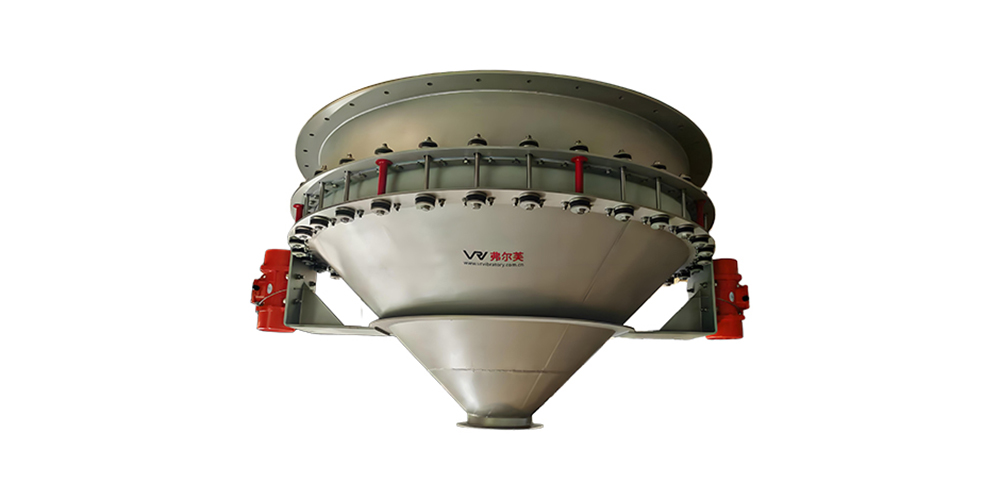
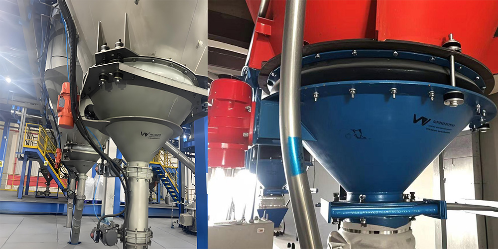
Bin activator, also known as Vibrating bottom, is a crucial device used to facilitate the smooth flow of bulk materials from storage bins, silos, or hoppers. It is usually conical in shape, made of steel or stainless steel, featuring a weldless structure with flange joint connections at the top and bottom, bin connection brackets, and one or two electric vibrators. For example, the Bin activator of VRV Company has a flexible connection between its conical bottom and the bin through a special bracket and a silicone soft connection, ensuring the transmission of vibration and the flow of materials while preventing leakage.

Bin activator

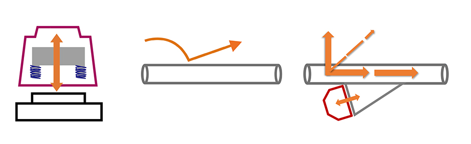
Based on the converging principle of the cone, when bulk dry materials are discharged from upstream equipment (such as bins) to downstream equipment (such as feeders or containers), the materials move from the large-diameter inlet of the Bin activator to the small-diameter outlet. The controllable vibration generated by the vibrating motor is transmitted to the bulk dry materials in the bin, causing the materials to flow smoothly and be discharged from the bin at a uniform rate, preventing blockages. The Bin activator can break up bridging, rat-holing, or accumulation of materials that may occur in the bin and promote the flow of bulk dry materials from storage bins or hoppers. For example, in some flour mills, the Bin activator can effectively solve the problem of poor discharging of flour caused by factors such as moisture absorption, ensuring the continuity of the production process. In addition to this, the Bin activator is also widely used in industries such as food, pharmaceuticals, and chemicals to handle various bulk dry materials such as powders, granules, and pills. In the food industry, for example, it can be used to handle materials such as coffee beans, wheat, and sugar; in the pharmaceutical industry, it can be used to handle pharmaceutical granules and powdered active pharmaceutical ingredients.

Bin activator

The Silo bin activators have the following advantages:

1. It stabilizes the discharging flow rate, ensuring the continuity of subsequent processes.

2. It features a compact structure and flexible installation, without taking up additional space.

3. It has low energy consumption and low wear, resulting in low long-term operating costs.

4. It is adaptable to a variety of materials, including highly viscous, highly hygroscopic materials, ultra-fine powders, and large granular materials.

5. It reduces the risk of manual intervention and requires no maintenance during long-term operation.

VRV is a leading vibrating bottom manufacturer in China providing best solution of bulk materials handling. We have supplied wide kind of bin activators to the clients from all over the world. Contact us, we will provide you high quality bin activators with the most competitive price.

Vibrating bottom

What’s the Best Way to Maintain an EV Charger to Extend Its Lifespan?

An EV charger is a long-term investment for electric vehicle owners and operators—but its lifespan depends heavily on regular maintenance. Skipping simple upkeep can lead to frequent breakdowns, slower charging, or even safety risks. Below are the most actionable steps to keep your charger running reliably for years.​


Regular Cleaning: Stop Damage Before It Starts​

External Cleaning​

Dust, rain residue, or spilled liquids (like garage cleaners) build up on your charger over time, seeping into ports or corroding casings. After each use, wipe the exterior and cable with a dry, lint-free cloth. For sticky stains, use a damp cloth with mild soap—avoid harsh chemicals that harm insulation. Check the charging port weekly with a soft brush to clear debris; blocked ports cause overheating.​


Internal Cleaning​

Internal dust can short-circuit components, but never open the charger yourself. For home or commercial units (like those in an operating charging station), hire a certified technician to blow out dust with compressed air once a year—this is especially critical for high-use models.​


Electrical System Checks: Catch Issues Early​

Voltage and Current Monitoring​

Fluctuations in power damage chargers over time. For a 7KW home charger, use a basic voltage tester monthly to ensure it’s receiving stable power (120V/240V, depending on your setup). At operating charging stations, invest in smart monitoring tools to track current—spikes often signal wiring issues that need immediate fixes.​


Circuit Inspection​

Check the charger’s plug, outlet, and internal wiring (via a technician) every 3–6 months. Look for loose connections or discolored plugs—these are signs of overheating that can ruin the charger.​


Thermal Management: Prevent Overheating​

Overheating is the top cause of AC charger failure. Keep your charger in a shaded, well-ventilated area (avoid direct sunlight or enclosed spaces). For outdoor units, install a waterproof cover with vents. Every 2 months, clean the charger’s 散热 grilles with a dry brush to remove dust—blocked grilles trap heat.​


Quick Habits: Handle and Store Wisely​

Never yank the charging cable—pull by the plug to avoid fraying wires.​

When not in use, coil the cable loosely (don’t twist it) to prevent internal damage.​

For seasonal storage (e.g., winter garages), keep the charger in a dry area above 0°C to avoid freezing damage.​

Simple, consistent maintenance—cleaning, electrical checks, and careful handling—will double your EV charger’s lifespan. By following these steps, you avoid costly repairs and ensure your charger (whether a 7KW home model or an AC charger at an operating charging station) stays reliable for years.

Why are reliability and efficiency key when EV chargers must run all day, all night, and serve drivers quickly?

Reliability and efficiency are critical for EV chargers, especially in high-traffic public and commercial environments where uptime directly impacts both user satisfaction and business operations. As a high quality EV charger manufacturer, USTEU designs its products to operate continuously, delivering consistent performance without interruptions. For drivers, reliable chargers mean they can plug in their vehicles anytime—day or night—without worrying about malfunctions or delays, ensuring a smooth and convenient charging experience.


Efficiency also plays a vital role in these scenarios. In busy locations such as shopping centers, office buildings, hotels, and highway service stations, chargers must manage energy precisely to serve multiple users quickly while minimizing downtime. USTEU systems provide high-power output with intelligent energy management, allowing operators to serve more vehicles simultaneously and maintain steady charging speeds. This efficiency reduces waiting times for drivers and helps businesses maximize throughput, operational capacity, and customer satisfaction.


Furthermore, USTEU integrates smart technologies to enhance both reliability and efficiency. As a provider of smart electric vehicle charging stations, USTEU chargers feature real-time monitoring, automated protection mechanisms, and intuitive interfaces. These features prevent faults before they occur, ensure optimal energy usage, and allow operators to monitor and manage their stations remotely. For commercial operators offering fast DC charging solutions for business, these capabilities are essential to maintain a competitive edge, as rapid and dependable charging attracts more customers and keeps fleet operations running smoothly.


In addition to technology, USTEU emphasizes durable construction and high-quality materials, ensuring that every charger withstands continuous operation in diverse environmental conditions. This combination of robust engineering, intelligent design, and efficient power management guarantees that USTEU chargers can run reliably around the clock, providing drivers with the convenience they expect and operators with the operational confidence they need.


In summary, reliability and efficiency are key because they directly affect user experience, business performance, and long-term operational sustainability. By offering durable, high-performance chargers equipped with smart management features, USTEU ensures that both everyday drivers and commercial operators can depend on their EV charging infrastructure to operate efficiently, safely, and consistently at all times.

Advanced High-Precision Equipment from Kezhen industries

Here in Kezhen, through over 20 years of purchasing equipment continuously, we have complete processing machines to meet your customized needs of high precision, high efficiency and high reliability manufacturing.


Even in order to control our products’ quality, we have self-made core special equipment including CNC external thread grinding, CNC internal thread grinding, testing instruments, and even tooling fixtures and tools are completed independently. We control the entire vertical industry chain and process to ensure the consistent product quality.


There are the latest 4 anodizing lines to producing anodized components.Our production technology achieves a smooth and uniform surface finish with roughness values (Ra) as low as 0.5µm and anodized thicknesses ranging from 0.5-150 µm. Widely applicable to aluminum, zinc, magnesium, titanium and other non-ferrous metals and alloys. No matter how these materials are made, whether it's CNC machining, sheet metal, extrusion or any other method, we can meet your requirements well. Send us your inquiries today!

What Are Linear Motion Parts and Where Are They Used?

If you’ve ever pulled open a desk drawer, watched a sliding glass door move effortlessly, or noticed the quiet motion of a hospital bed adjusting, you’ve seen linear motion in action. Unlike rotation, which turns around an axis, linear motion is all about moving smoothly in a straight line. The parts that make this possible are called linear motion components, which also are the main products in Kezhen Industries.


What Exactly Are Linear Motion Parts?

Linear motion parts are mechanical elements that make straight-line movement possible. Think of them as the “tracks” and “drivers” that keep things moving in one controlled direction. Instead of wheels or gears that spin, these parts are designed to guide, support, and move loads along a single path.


Some of the most common examples include:

Linear bearings and bushings – These minimize friction while allowing a shaft to glide.

Guide rails – Provide a smooth track for machines or equipment.

Rolled Ball screws and lead screws – Convert rotary motor power into precise forward and backward motion.

Linear actuators – Compact systems that push or pull objects with controlled force.

In simple terms, they’re the building blocks that transform energy into predictable, straight-line motion.


Why Are They Important?

Imagine trying to build a CNC machine or a robotic arm without components that keep everything aligned. The result would be jerky, inaccurate, and unreliable. Linear motion parts solve this by:


Improving accuracy – Achieving micrometer-level positioning.

Handling heavy loads – Supporting industrial machinery with minimal wear.

Reducing energy loss – Their low-friction designs make operations smoother and more efficient.

Without them, many of the things we take for granted in automation and daily life simply wouldn’t work.


Everyday and Industrial Applications

Linear motion technology appears in places we often overlook.

Manufacturing

CNC machines, 3D printers, and robotic assembly lines all rely on linear guides and high precision ball screws to move tools with high precision.

Medical Devices

From MRI scanners to adjustable hospital beds, linear actuators ensure smooth, safe movements for patients and doctors.

Semiconductor Industry

Here, accuracy is measured in microns. Linear stages carefully move wafers during production, where even the tiniest vibration matters.

Transportation

Aircraft seating adjustments, train systems, and even space technology depend on reliable straight-line movement.

Daily Life

Sliding doors, office printers, and motorized home furniture use scaled-down versions of these parts.


How to Choose the Right Linear Motion Parts

Not all linear motion components are created equal. The right choice depends on the application, environment, and performance needs. Here are some key factors to consider:

Load capacity: Heavy industrial machines need robust rails and bearings, while lightweight consumer devices may only require compact actuators.

Precision requirements: For semiconductor or medical industries, ball screws with extremely low backlash are critical. For furniture or doors, basic rails may be sufficient.

Speed and travel length: Some applications require long, smooth travel, while others demand quick, short movements.

Environmental conditions: Dust, moisture, or temperature extremes can affect performance. Specialized coatings or sealed bearings might be necessary.

Maintenance needs: Choosing parts designed for easy lubrication or low upkeep can save long-term costs.


As automation, robotics, and smart devices expand, the demand for linear motion solutions is only growing. We’re already seeing parts integrated with sensors and IoT connectivity, allowing real-time monitoring and predictive maintenance. On the consumer side, compact actuators are making their way into home automation, while heavy-duty systems are supporting renewable energy projects like solar tracking.


Linear motion parts don’t usually steal the spotlight, but they’re the quiet enablers behind countless innovations. Next time you notice something moving smoothly in a straight line—whether it’s a high-tech robot or just your sliding window—you’ll know there’s some clever engineering making it happen.

Analysis and Countermeasures of Reverse Rotation of Rod Column in Screw Pump Well

Regarding some questions about screw pumps, Anhui Shengshi Datang would like to share some insights with everyone.

  Causes and Hazards Analysis of Rod String Reverse Rotation in Screw Pump Wells

1. Analysis of Causes for Rod String Reverse Rotation in Screw Pump Wells

During oilfield extraction using Screw Pumps, reverse rotation of the rod string is a relatively common failure. The causes of this reverse rotation are complex, but the primary reason is the sudden shutdown or sticking of the pump during operation, which causes deformation and torsion of the rod string. The rapid release of this deformation and torsion then leads to reverse rotation. Specifically, if the Screw Pump suddenly stops or sticks during operation, a pressure difference arises between the high-pressure liquid retained in the production tubing and the wellbore hydrostatic pressure in the casing annulus. Driven by this pressure difference, the Screw Pump acts as a hydraulic motor, driving the rotor and the connected rod string to rotate rapidly in reverse.

The reverse rotation of the Screw Pump rod string is influenced by the tubing-casing pressure difference, exhibiting variations in reverse rotation duration and speed. Generally, a larger tubing-casing pressure difference results in faster reverse rotation speed and longer duration for the rod string. As the pressure difference gradually decreases, the reverse rotation speed and duration correspondingly decrease until the pressure difference balances, at which point the reverse rotation gradually ceases. When reverse rotation occurs, the rod string vibrates intensely. If resonance occurs during this vibration—meaning the vibration frequency of the reversing rod string synchronizes with the natural frequency of the wellhead—the rotation speed can instantly surge to its maximum. This situation can trigger serious safety accidents, cause significant harm to the worksite, and even result in casualties.

2. Hazards of Rod String Reverse Rotation in Screw Pump Wells

The hazards caused by rod string reverse rotation vary in degree depending on the speed and duration of the reversal. Severe cases can lead to onsite safety incidents with serious consequences. Specifically, the hazards mainly manifest in the following three aspects:

(1) Reverse rotation can cause the rod string to become displaced from its original position, leading to the swinging of the Screw Pump polish rod. This can cause significant wear and tear on the Screw Pump equipment, damaging various components and parts.

(2) During reverse rotation, if the speed is too high or the duration too long, the temperature of the reversing components can continuously rise, potentially igniting flammable gases at the wellhead. This could trigger an explosion at the worksite, leading to unforeseeable serious consequences.

(3) If reverse rotation is not effectively controlled, it can cause the drive pulley to shatter. Fragments of the pulley flying around the worksite pose a risk of injury to personnel, damage the oilfield production site, reduce extraction efficiency, and increase the probability of various safety incidents.
  Commonly Used Anti-Reverse Rotation Devices for Screw Pump Well Rod Strings

1. Ratchet and Pawl Type Anti-Reverse Device

This type of device prevents reverse rotation by utilizing the one-way engagement of a ratchet and pawl. Specifically, the ratchet and pawl engage via an external meshing configuration. When the Screw Pump drive operates normally, centrifugal force causes the pawl to disengage from the ratchet brake band, so the anti-reverse device remains inactive. However, when the Screw Pump suddenly stops during operation, the rod string begins to reverse due to inertia. During this reverse rotation, gravity and spring force cause the pawl to engage with the ratchet brake band, activating the anti-reverse device. The device then dissipates the torque generated by the high-speed reverse rotation through frictional force.

The ratchet and pawl device has a simple structure, is easy to install, has a low overall cost, and offers good flexibility and controllability. However, it typically requires manual intervention at close range for activation/operation. Improper operation can cause the friction surfaces to slip, presenting a safety risk. Additionally, this type of device can generate significant noise during operation and subjects the components to considerable impact and wear, necessitating frequent part replacements.

2. Friction Type Anti-Reverse Device

The friction type anti-reverse device consists of two main parts: an overrunning clutch that identifies rotation direction and a brake shoe assembly. In this device, the brake shoes are connected to the brake bodies via riveting, and the two brake bodies grip the outer ring. During normal Screw Pump operation (clockwise rotation), the device remains inactive. When a sudden shutdown causes reverse rotation, the drive mechanism reverses. In this state, rollers move between the star wheel and the outer ring, activating the device. The resulting damping effect restricts the rotation of the star wheel, thereby achieving the anti-reverse function. However, since the operation of this device often requires manual control, improper handling can lead to failure. Furthermore, replacing this device involves significant safety risks. Consequently, its application in Screw Pump wells is currently relatively limited.

3. Sprag Type Anti-Reverse Device

The sprag type anti-reverse device operates based on the principle of an overrunning clutch. Specifically, during normal Screw Pump operation (forward rod string rotation), the sprags inside the device align normally and remain disengaged from the outer ring, keeping the device inactive. When the pump suddenly stops and the rod string starts to reverse rotate, the resulting reverse torque causes the device to rotate in the opposite direction. This makes the sprags align in the reverse direction, locking them against the outer ring and preventing reverse rotation of the rod string.

The sprag type device has a simple construction, is easy to install, offers good controllability, and operates with high safety, minimizing the risk of accidents. It also has a long service life and does not require frequent part replacements. The drawback is that it cannot fundamentally solve the reverse rotation problem. If the reverse torque exceeds the capacity the sprags can withstand, it can cause sprag failure and device malfunction. Additionally, daily maintenance of this device can be inconvenient.
4. Hydraulic Type Anti-Reverse Device

The working principle of the hydraulic anti-reverse device is somewhat similar to a car's braking system. When the Screw Pump suddenly stops and the rod string is about to reverse rotate, the hydraulic motor within the device activates. Hydraulic fluid pressure drives friction pads against a brake disc, releasing a large amount of the reverse rotation potential energy, thereby dissipating the reverse rotation of the rod string.

The advantages of the hydraulic type device include stable and reliable operation, high safety, no noise generation, and no hazard to onsite personnel. Maintenance, replacement, and daily upkeep are relatively convenient and safe. This type of device can more thoroughly address the reverse rotation problem, enhancing the operational safety of the Screw Pump system. The disadvantages are its high overall cost and stringent quality requirements for the hydraulic components, leading to potentially higher maintenance and replacement costs. If issues like hydraulic fluid degradation or leaks occur during operation, the device's performance can be affected, necessitating regular maintenance.

  Measures to Address Rod String Reverse Rotation in Screw Pump Wells

1. Research and Application of Safer, More Reliable Anti-Reverse Devices

Analysis of the causes of rod string reverse rotation indicates that the main factors are the release of stored elastic potential energy in the rod string and the effect of the tubing-casing pressure difference. If reverse rotation is not effectively controlled, especially at high speeds or for prolonged durations, it can lead to a series of severe consequences and safety incidents, posing significant risks. Therefore, technical research and application should be strengthened. Based on existing anti-reverse devices, upgrades and improvements should be made to develop and apply safer and more reliable devices. These should ensure the safe release of torque and effective elimination of the pressure difference during sudden Screw Pump shutdowns, reducing associated safety risks. The working principles, advantages, and disadvantages of common anti-reverse devices need in-depth analysis for targeted improvements. This will enhance the stability and reliability of these devices, minimize safety risks during use, and maximize the operational safety of Screw Pump equipment.

2. Application of Downhole Anti-Backflow Switches

Using downhole anti-backflow switches can effectively address reverse rotation caused by hydraulic forces. The downhole anti-backflow switch consists of components like a disc, ball, push rod, shear pin, and crossover sub. Its application in the Screw Pump drive system can reduce the torque generated during sudden shutdowns, lower the reverse rotation speed, and mitigate reverse rotation caused by the tubing-casing pressure difference. By dissipating hydraulic forces, it helps control reverse rotation and also prevents rod string back-off. The anti-backflow switch has a simple structure, low cost, and is easy to install. It has been widely used in oilfield development due to its strong stability, high reliability, and broad application prospects.

3. Strengthening Surface Safety Management

To effectively control reverse rotation, it is essential not only to equip Screw Pump systems with appropriate anti-reverse devices but also to enhance safety management in surface operations and implement protective measures to reduce the adverse consequences of reverse rotation. Specific measures include:

① Personnel should perform daily inspection, maintenance, and servicing of Screw Pump equipment, maintain proper equipment management records, continuously accumulate experience, and improve safety prevention capabilities.

② Implement continuous monitoring of the Screw Pump system's operation to promptly detect abnormalities. Take immediate action for fault diagnosis and troubleshooting to reduce the probability of reverse rotation occurrences.

③ Establish comprehensive emergency response plans. For sudden reverse rotation events, immediately activate the emergency plan to lower the probability of safety incidents.
Analysis of the Working Principle and Causes of Cavitation in Centrifugal Pumps

Working Principle of Centrifugal Pumps

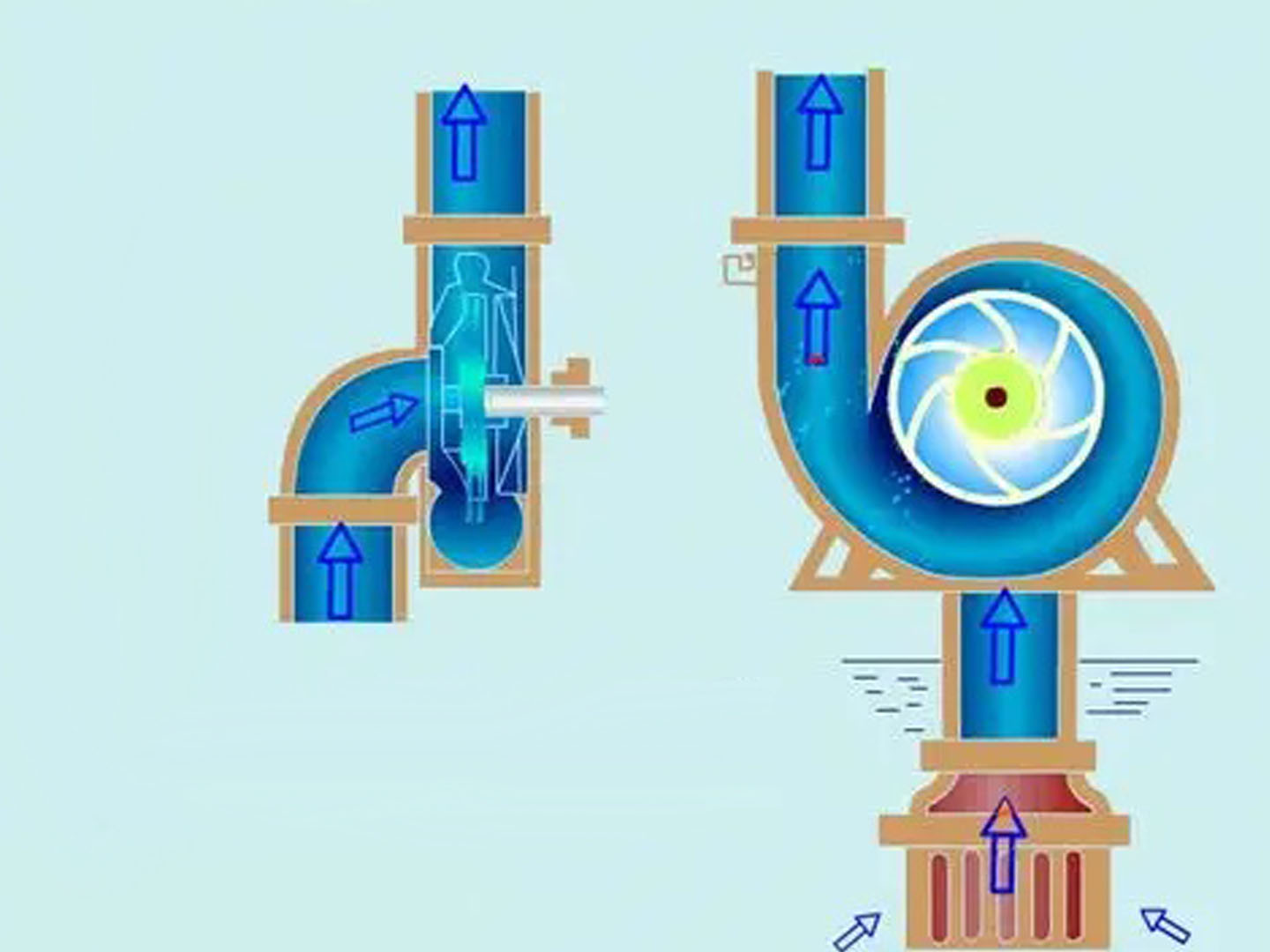
The working principle of centrifugal pumps is based on the action of centrifugal force. When the impeller rotates at high speed, the liquid is thrown from the center of the impeller to the outer edge under the influence of centrifugal force, thereby gaining kinetic energy and pressure energy. The specific working process is as follows:

1.Liquid enters the central area of the impeller through the pump's suction inlet.

2.The rotation of the impeller generates centrifugal force, causing the liquid to move from the center of the impeller to the outer edge along the blade passages.

3.The liquid gains kinetic energy and pressure energy within the impeller and is then discharged into the pump casing.

4.Inside the pump casing, part of the liquid's kinetic energy is converted into pressure energy, and the liquid is ultimately discharged through the outlet.

During the operation of a centrifugal pump, the impeller does work by converting mechanical energy into the energy of the liquid. As the liquid flows through the impeller, both its pressure and velocity increase. According to Bernoulli's equation, the increase in the total energy of the liquid is primarily manifested as an increase in pressure energy, enabling the centrifugal pump to transport the liquid to a higher elevation or overcome greater system resistance.

It is important to note that the prerequisite for the normal operation of a centrifugal pump is that the pump cavity must be filled with liquid. This is because centrifugal force can only act on liquids and not on gases. If air is present in the pump cavity, the pump will be unable to build up pressure normally, resulting in "vapor lock," which ultimately leads to cavitation.

Analysis of Causes for Centrifugal Pump Cavitation

 1.Inadequate Inlet Medium or Insufficient Inlet Pressure

Inadequate inlet medium is one of the most common causes of centrifugal pump cavitation. The following situations may lead to insufficient inlet medium:

a. Low Liquid Level: When the liquid level in a pool, tank, or storage container falls below the pump's suction pipe or the minimum effective level, the pump may draw in air instead of liquid, resulting in cavitation.

b. Excessive Suction Lift: For non-self-priming centrifugal pumps, if the installation height exceeds the allowable suction lift, even if the suction pipe is immersed in the liquid, the pump will be unable to draw the liquid up, leading to a lack of liquid inside the pump. According to physical principles, the theoretical maximum suction lift for non-self-priming centrifugal pumps is approximately 10 meters of water column (atmospheric pressure value). However, considering various losses, the actual suction lift is typically below 6-7 meters.

c. Insufficient Inlet Pressure: In applications requiring positive inlet pressure, if the provided inlet pressure is lower than the required value, the pump may experience inadequate liquid supply, causing cavitation.

d. Poor System Design: In some system designs, if the suction pipeline is too long, the pipe diameter is too small, or there are too many bends, the pipeline resistance increases, reducing the inlet pressure and preventing the centrifugal pump from drawing liquid properly.

Case studies show that approximately 35% of centrifugal pump failures in the petrochemical industry are caused by inadequate inlet medium or insufficient inlet pressure. This issue is particularly common in oil transportation systems due to the high viscosity and vapor pressure of oil products.


 2.Blockage in the Inlet Pipeline

Blockage in the inlet pipeline is another common cause of centrifugal pump cavitation. Specific manifestations include:

a. Clogged Screens or Filters: During long-term operation, screens or filters in the inlet pipeline may become gradually blocked by impurities or sediments, restricting liquid flow.

b. Scale Formation Inside the Pipeline: Particularly when handling hard water, water with high calcium and magnesium ion content, or specific chemical liquids, scale or crystalline deposits may form on the inner walls of the pipeline, reducing the effective diameter over time.

c. Foreign Object Entry: Accidental entry of objects such as leaves, plastic bags, or aquatic plants into the suction pipeline can block elbows or valves, obstructing liquid flow.

d. Partially Closed Valves: Operational errors, such as failing to fully open valves in the suction pipeline, or internal valve malfunctions, can also lead to insufficient flow.

e. Foot Valve Failure: In systems equipped with foot valves, if the foot valve malfunctions (e.g., spring deformation or sealing surface damage), it can affect the pump's ability to draw liquid properly.

Statistical data indicate that approximately 25% of centrifugal pump cavitation cases in municipal water supply and drainage systems are caused by inlet pipeline blockages. This issue is especially common in wastewater treatment systems with high levels of suspended solids.


 3.Incomplete Air Removal from the Pump Cavity

Incomplete air removal from the pump cavity is a significant cause of centrifugal pump cavitation. Key manifestations include:

a. Inadequate Priming Before Initial Startup: After initial installation or prolonged shutdown, centrifugal pumps must be primed to remove air from the pump body. If priming is insufficient, residual air can prevent the pump from establishing normal working pressure.

b. Insufficient Self-Priming Capability: Non-self-priming centrifugal pumps cannot expel air on their own and rely on external priming. While some self-priming pumps have a certain self-priming capability, improper startup methods or excessive self-priming height can lead to poor air expulsion.

c. Air Leaks in the Pipeline System: Minor cracks in suction pipeline connections, sealing points, or aging pipes can allow air to enter the system under negative pressure. This is particularly hazardous because even if the pump is initially primed correctly, air can accumulate over time, eventually causing cavitation.

d. Seal Failure: Worn or improperly installed shaft seals (e.g., mechanical seals or packing seals) can allow external air to enter the pump, especially when the suction side pressure is below atmospheric pressure.

In industrial applications, approximately 20% of centrifugal pump cavitation cases are caused by incomplete air removal from the pump cavity. This issue is particularly common during initial startup after installation or maintenance.


 4.Other Causes

In addition to the main causes mentioned above, other factors can also lead to centrifugal pump cavitation:

a. Liquid Vaporization: When handling high-temperature or highly volatile liquids, if the suction pipeline pressure falls below the liquid’s saturation vapor pressure at that temperature, the liquid may vaporize, forming bubbles. This can prevent the pump from drawing liquid or cause cavitation.

b. Operational Errors: Human factors, such as incorrect valve operation or failure to follow startup procedures, can lead to pump cavitation.

c. Control System Malfunctions: In automated control systems, failures in level sensors, pressure sensors, or errors in PLC programming logic may cause the pump to start or operate under inappropriate conditions, resulting in cavitation.

d. Power or Motor Issues: Incorrect power phase sequence causing motor reversal can prevent the pump from drawing liquid properly. Voltage instability causing motor speed fluctuations can also disrupt normal pump operation.

e. Temperature Effects: In extreme environmental conditions, such as cold regions, inadequate insulation may cause liquid in the pipeline to freeze, obstructing flow. In high-temperature environments, liquids may vaporize, forming vapor locks.

Research indicates that these other causes account for approximately 20% of centrifugal pump cavitation cases. Although the proportion is relatively small, they can be significant factors in specific scenarios or conditions and should not be overlooked.