Have you ever picked a water cooled screw chiller factory just because it was cheap or someone told you to? Many people do this and end up paying more or having problems with their system. You need a partner you can trust, not just any supplier. Choosing carefully helps you stop breakdowns and expensive fixes. Go slowly and follow steps to keep your money safe and make sure your building works well.
Key Takeaways
Find out what cooling your building needs. Pick a chiller size that fits. Make sure the setup works well every day.
Look at the factory's certifications. Check if people trust the factory. This helps you know it is safe and good quality.
Pick chillers made with strong materials. Make sure they are tested well. This helps them last long and save energy.
Choose a factory with good help after you buy. They should answer questions fast. Manuals should be easy to read. Warranties should be strong. This keeps your system working.
Do not pick just by price. Think about all costs. Energy, fixing, and repairs matter too. This gives you better value.
Requirements Assessment
Cooling Capacity
First, you need to know how much cooling your building needs. Check the size of your building and the heat from your machines. Think about what kind of work happens in your building. These things help you pick the right chiller size and setup. If you pick a water cooled screw chiller, make sure it can handle your daily needs. This helps it work well every day.
Look at the temperature range you need for your system. Most chillers work best with a Delta T of about 15°F. Keep the chilled water above 39°F so it does not freeze. This also helps you avoid extra costs. The type of compressor matters too. Screw and centrifugal compressors work differently. They change how your chiller handles different loads.
You should think about how many chillers you need. Having more than one chiller gives you backup. It also helps your system work better when you do not need full power. Make sure your pumps keep water moving at the right speed and pressure. This helps your water cooled screw chiller work well and last longer.
Tip: Think about the future. If you might need more cooling later, pick a chiller system that can grow with you.
Budget and Timeline
Set your budget before you start looking. Do not just count the chiller price. Add the cost for installation, cooling towers, pumps, and maintenance. Energy efficiency is important. A more efficient water cooled screw chiller may cost more at first. But it saves you money over time.
Think about how long your project will take. Some chillers take longer to get, especially if you want special features. Make sure the factory can deliver on time. This helps you avoid delays.
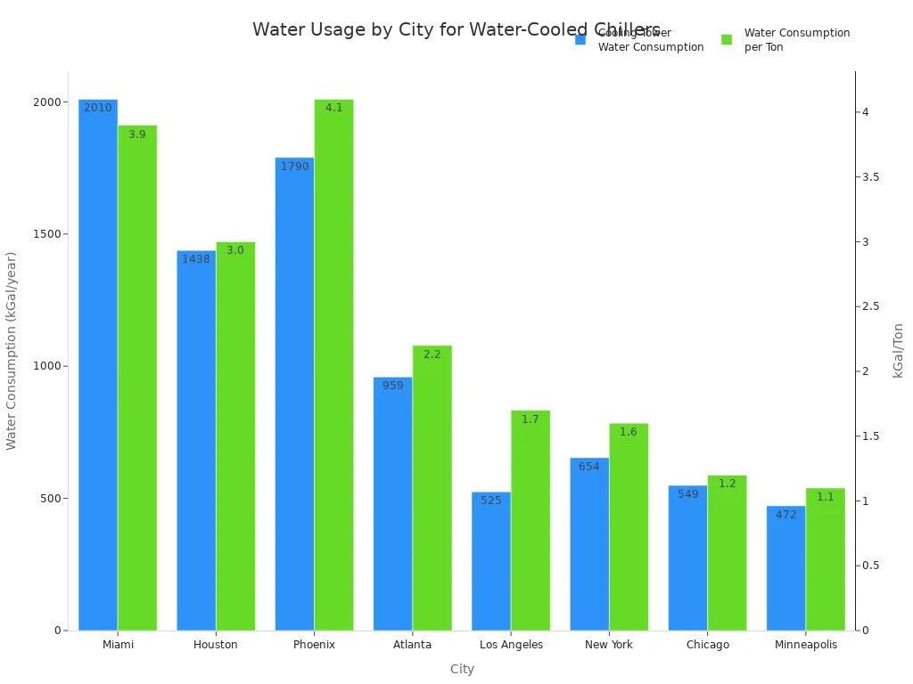
Check the water quality at your building. Bad water can hurt your chiller and make it less efficient. Plan for water treatment if you need it. Always check your needs to make sure the chiller is right for you.

Water Cooled Screw Chiller Factory Research
Credentials and Compliance
When you pick a water cooled screw chiller factory, check their credentials. These show if the factory follows the rules and meets standards. If you skip this, you might get a chiller that breaks or causes trouble with the law. A good water cooled screw chiller factory will show you their certifications.
Here is a table of important certifications and standards you should look for:
|
Certification / Standard
|
Relevance / Purpose
|
|
ISO 9001
|
Quality management system
|
|
ISO 14001
|
Environmental management system
|
|
Eurovent Certified Performance
|
Verified chiller performance and efficiency
|
|
CE
|
European health, safety, and environmental protection standards
|
|
RoHS
|
Restriction of hazardous substances
|
|
UL Listing
|
Safety certification for electrical components
|
|
ATEX Compliance
|
Safety in explosive atmospheres
|
|
EU Directives (Ecodesign, F-Gas)
|
Energy efficiency and refrigerant environmental regulations
|
You should always ask the water cooled screw chiller factory to show these certifications. Factories with these papers care about safety, quality, and the environment. This helps you avoid problems like broken equipment or getting in trouble with the law.
Note: Checking credentials and compliance keeps you safe from many risks. You do not buy from bad vendors, so your building and money stay safe.
Checking compliance helps you in other ways too:
You are less likely to get a chiller that breaks safety rules.
You avoid delays from failed checks or denied entry.
You lower the chance of fines or legal trouble.
You make sure your water cooled screw chiller factory uses safe materials.
Experience and Reputation
You should check how much experience the water cooled screw chiller factory has. A factory with many years knows how to fix problems and make good chillers. Ask how long they have made chillers and how many jobs they have done.
A good reputation means customers are happy and trust the factory. You can check this by:
Reading reviews and stories from other buyers.
Asking for examples of past projects.
Seeing if the factory has worked with big companies.
A good water cooled screw chiller factory can also make special chillers for you. They will listen to what you need and give you choices that fit your building. Custom work shows the factory understands different jobs and can help with special needs.
Tip: Pick a water cooled screw chiller factory that has both regular and custom chillers. This gives you more choices and better results.
When you choose a factory with good credentials, experience, and a strong reputation, you lower your risks. You get a chiller that works well, lasts longer, and follows all the rules. This step helps you build a safe and strong cooling system for your business.
Chiller Selection and Product Quality
Manufacturing Process
When you pick a water cooled screw chiller, look at how the factory makes it. Good chillers start with smart design and strong engineering. The team learns what you need and plans for good performance and long life. They choose strong materials like stainless steel and copper for important parts. Skilled workers build the evaporator, condenser, compressor, and refrigerant circuit with care.
Here are the main steps in making a chiller:
-
Design and engineering for your project’s needs.
-
Careful material selection for durability.
-
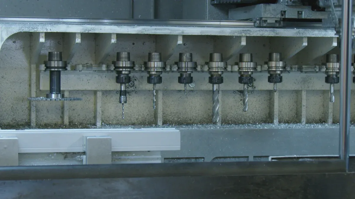
Precision manufacturing of all main components.
-
Assembly with expert wiring and plumbing.
-
Rigorous testing for leaks, performance, and safety.
-
Custom adjustments to match your requirements.
-
Safe delivery and proper installation.
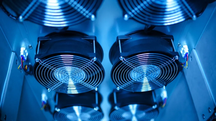
A good chiller uses water to take heat and move it to the refrigerant. The condenser sends this heat to a cooling tower. Fans blow the heat into the air. Screw chillers use helical rotors in the compressor to pressurize refrigerant well. This design helps with high tonnage and keeps chiller performance steady.
Tip: Always ask to see how the factory tests chillers. Good testing makes sure your chiller works well and meets your needs.
Specifications and Innovation
You should check the chiller’s specifications and look for new features that help it work better. Top factories use advanced twin-screw compressors for better stability and less leakage. They add smart oil management and special heat exchangers to make chiller performance and energy savings better.
Modern chillers have:
Stepless capacity control for matching loads.
Microcomputer controls with touch screens and warning logs.
Safety features like anti-freezing and pressure protection.
Options for building management system integration.
Some chillers use special copper tubes with spiral grooves to boost heat transfer by up to 30%. These upgrades help you get better chiller performance and lower costs. Top brands focus on efficiency, reliability, and long life. With good care, your chiller can last 15 to 20 years or more.
Note: Regular maintenance, water treatment, and daily checks help your chiller last longer and work well.
After-Sales Support
Warranty and Maintenance
You need good after-sales help to keep your system working well. A strong warranty helps you feel safe. It pays for repairs or new parts if something breaks soon after you buy it. Always check what the warranty covers and how long it lasts. Some warranties only pay for parts, but others pay for labor and service too.
Regular maintenance is very important for your system. If you do routine checks, you can stop problems like blocked condenser lines or dirty tubes. Maintenance teams clean cooling towers, check pumps, and watch system pressures. These steps help you find problems early and avoid big breakdowns. You also lower the chance of damage and help your equipment last longer.
Places that do regular maintenance have fewer problems and longer-lasting equipment. You save money by stopping emergency repairs and keeping your system working well.
A system that gets good care also stops things like bacteria growth and rust. These problems can make your system stop and work badly. If you follow a maintenance plan, your system stays safe and steady.
Technical Support
You should get great technical support from your supplier. Good support starts with clear guides and manuals. These papers help you set up and use your system the right way. Many people like having both paper and digital copies so they are easy to find.
Fast and expert help is very important. You want a team that answers your questions quickly, sometimes in minutes or hours. Most people want a reply to their emails in four hours. Quick answers make you happy and stop bigger problems. If you get help fast, you can fix things before they get worse.
24/7 expert help during setup and use
Free support and spare parts while under warranty
Special advice for your own needs
Help with future orders or upgrades
Fast support makes you trust your supplier and want to stay with them. Slow answers can make you look for a new supplier.
If you pick a supplier with strong technical support, you feel safe. You know help is always there, and your system will keep working right.
Common Mistakes in Selection
Price-Only Decisions
Some people pick a water cooled screw chiller factory just because it is cheap. This can cause problems and cost more later. Many buyers forget about energy bills and fixing costs. You should think about all the money you will spend, not just the first price.
Here is a table that shows what can happen if you only look at price:
|
Financial/Operational Impact
|
Details
|
|
High Startup Cost
|
Industrial chillers cost a lot at first. This scares buyers who only care about price.
|
|
Overlooked Operational Costs
|
If you ignore energy and fixing costs, you pay more later.
|
|
Risk of Inefficient Equipment
|
Less efficient chillers use more energy and cost more over time.
|
|
Higher Total Cost of Ownership
|
Picking the wrong chiller means more repairs and bad operation.
|
Better chillers may cost more when you buy them. They work better and need less fixing. If you only care about price, you might get a chiller that breaks a lot and uses too much energy. Always look at how much you will spend over many years.
Overlooking Support
You need good help after you buy your chiller. Some people forget to check if the supplier gives support. Without help, it takes longer to fix things and find new parts. This means your chiller stops working and costs more to repair. A good supplier gives easy-to-read manuals and quick help. They offer regular checks and fixing plans. Ask about the warranty and how fast they answer questions.
Good support helps you fix problems fast and keeps your chiller working well.
Tip: Pick a supplier that gives help all day and night. Make sure they have clear plans for fixing and checking your chiller.
Ignoring Reputation
Do not forget to check if the water cooled screw chiller factory is trusted. Good factories follow strict rules and test their chillers well. You can check this by looking at their papers and seeing how they build chillers. Trusted factories use special rooms to test chillers and give reports to buyers.
Here are steps to check if a factory is good:
-
Look at their technical papers and data sheets.
-
Check how they build chillers and main parts.
-
Make sure safety devices and systems work right.
-
Test how the chiller works with different loads.
-
Check if the shipment is ready and labeled right.
A trusted factory makes sure your chiller works for you. You save money and avoid mistakes by picking a supplier with a good name.
You can stop expensive mistakes if you follow clear steps. Doing good research and planning helps your system fit your needs. This is true for places like breweries and wineries. Real-life stories show that picking the right system saves energy and works better. It also helps your business stay strong for a long time. If you make smart choices, your system will work well and cost less for years. Take every step carefully so your business gets the best results.
FAQ
What is the most important factor when choosing a chiller factory?
You should focus on the factory’s experience and reputation. A trusted factory delivers reliable products and strong support. Always check reviews and ask for references before you decide.
How do I know if a chiller factory meets safety standards?
Ask the factory to show you their certifications. Look for ISO, CE, and UL marks. These prove the factory follows safety and quality rules. Never skip this step.
Why does after-sales support matter for chillers?
You need fast help if your chiller stops working. Good support means quick repairs and easy access to spare parts. This keeps your system running and protects your investment.
Can I customize a water cooled screw chiller for my building?
Yes, many factories offer custom solutions. You can ask for special sizes, controls, or energy-saving features. Tell the factory your needs so they can design the right system for you.