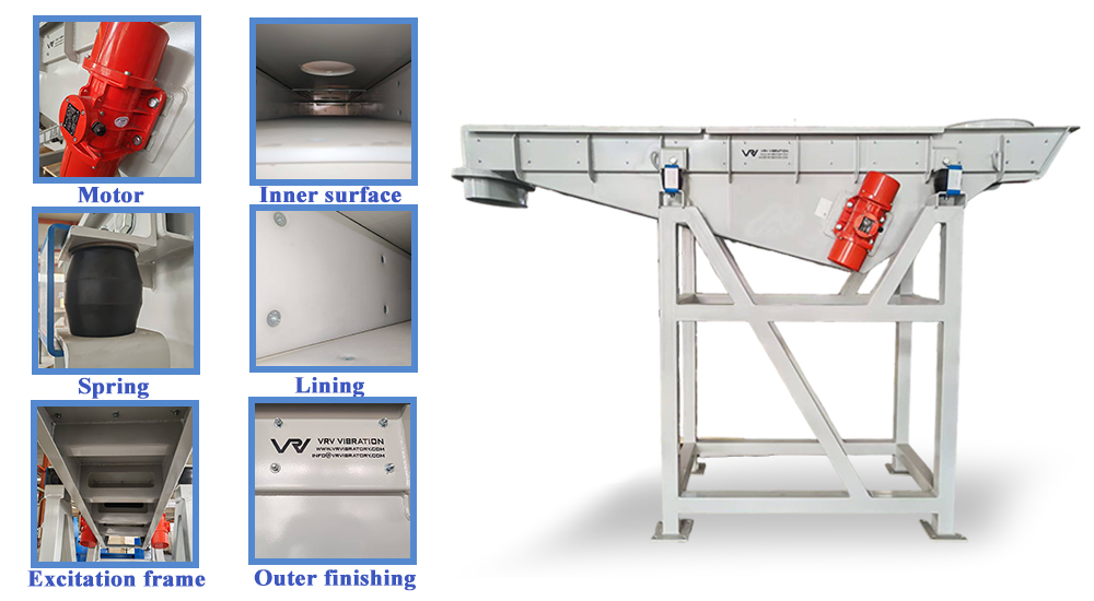
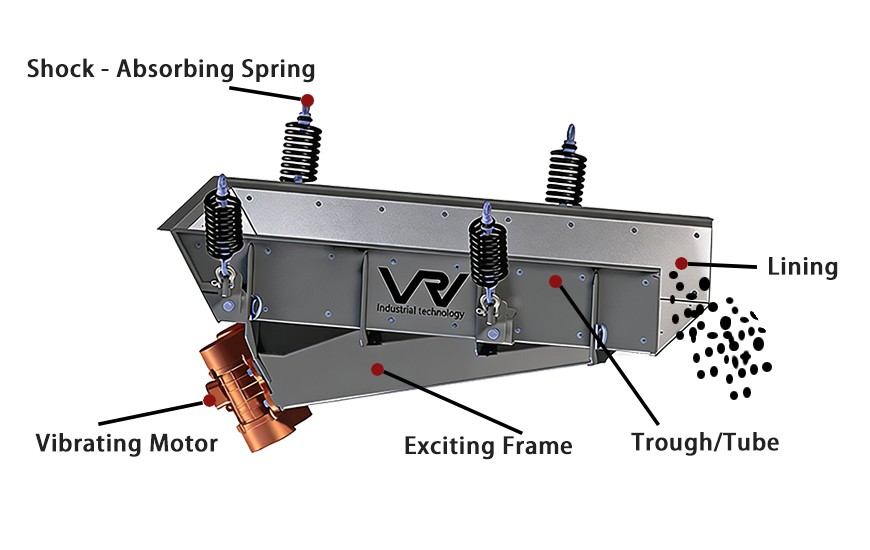
Maximizing Machine Uptime Preventative Maintenance for Heavy-Duty Balers and Shears

To maximize the lifespan and ROI of heavy-duty metal recycling machinery, facilities must implement a strict preventative maintenance schedule focusing on hydraulic fluid purity, daily cylinder seal inspections, and regular replacement of wear plates. Consistent maintenance prevents catastrophic hydraulic failures, reduces unplanned downtime, and ensures continuous high-volume throughput.

The True Cost of Unplanned Downtime In the highly competitive metal recycling industry, equipment downtime is the silent killer of profitability. When a heavy-duty processing machine suddenly breaks down, the financial impact extends far beyond the cost of replacement parts. It causes massive bottlenecks in the yard, delays outbound shipping contracts, and leaves expensive labor forces standing idle. For procurement managers and facility operators, protecting your capital investment means shifting from a reactive "fix-it-when-it-breaks" mentality to a proactive preventative maintenance strategy.

Protecting the Hydraulic Lifeblood The core of any modern compaction or cutting machinery is its hydraulic system. Whether you are operating a heavy-duty scrap metal baler or a massive gantry shear, hydraulic fluid acts as the lifeblood of the machine. The most common cause of catastrophic failure is fluid contamination.

Microscopic metal shavings, dust, and water condensation can bypass worn seals and enter the hydraulic reservoir. Over time, these contaminants act like liquid sandpaper, destroying expensive pumps and scoring hydraulic cylinders from the inside out. To prevent this, operators must strictly adhere to OEM guidelines regarding oil filter replacements and fluid sampling. Additionally, monitoring the hydraulic oil temperature is critical; running a machine with overheated oil rapidly degrades the fluid's viscosity and destroys internal O-rings.

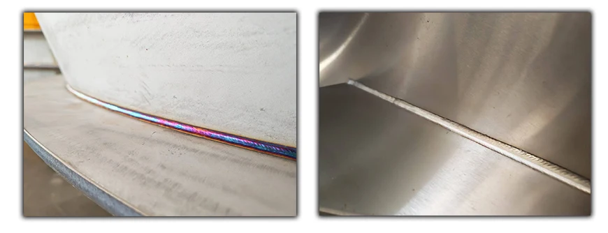
Inspecting Structural Integrity and Wear Parts Heavy machinery is subjected to immense, repetitive stress. Daily visual inspections are critical for catching small issues before they escalate. Operators should regularly check the structural integrity of the press chamber for micro-fractures along the weld lines.

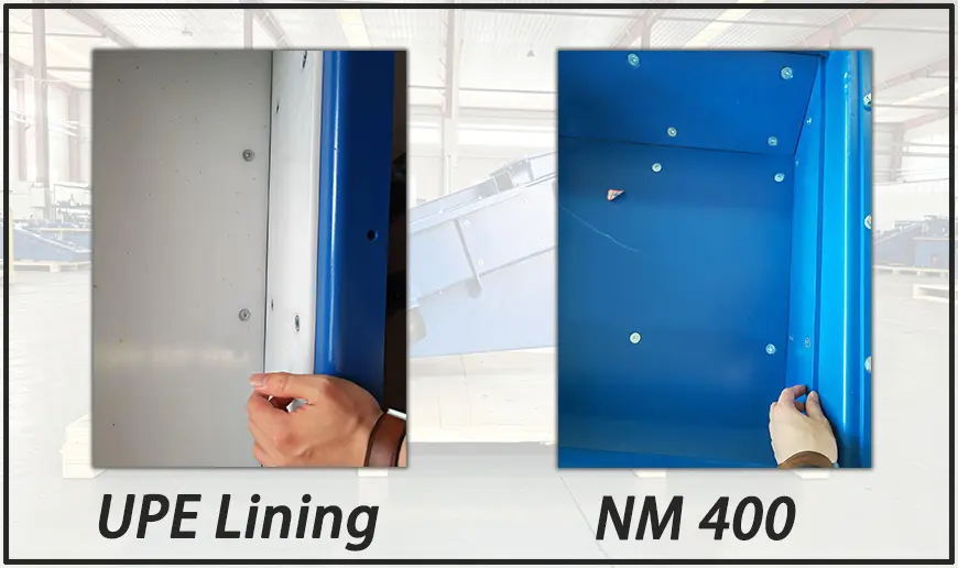
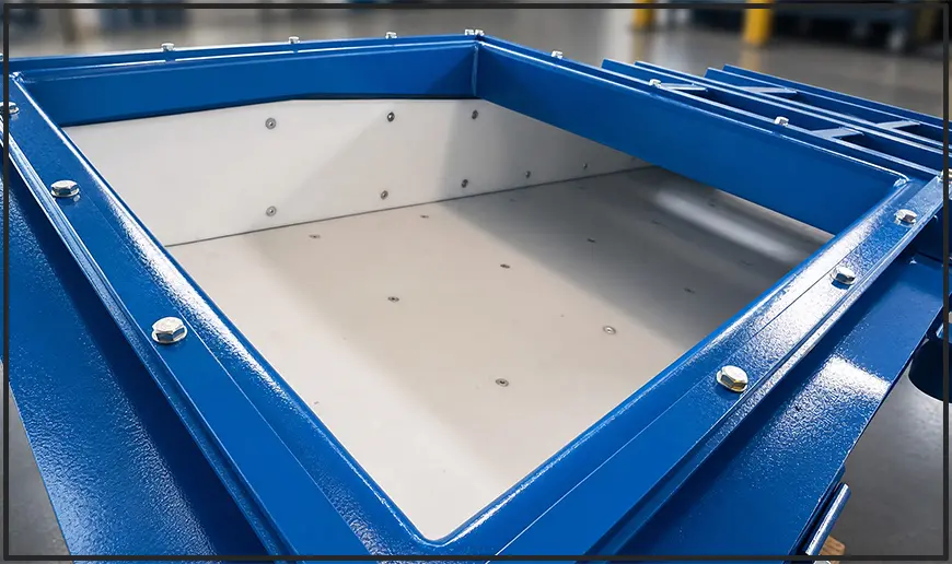
Furthermore, wear parts such as inner liner plates and cutting blades must be monitored. If you are utilizing an industrial scrap metal shear, operating with dulled blades forces the hydraulic system to work significantly harder to achieve the same cut. This spikes electrical energy consumption and places unnecessary strain on the motors. Regularly rotating or replacing hardened alloy blades ensures clean, efficient cuts and protects the machine's primary drive systems.

Partnering for Long-Term Success Ultimately, the longevity of your recycling equipment depends on a combination of rigorous daily maintenance and rapid access to high-quality spare parts. When sourcing machinery, partnering with a manufacturer that provides comprehensive maintenance training, intuitive PLC diagnostic systems, and a reliable global supply chain for replacement parts is essential for keeping your yard running at peak capacity year after year.

Choosing a Professional Scrap Metal Shear Manufacturer Engineering for Performance

Selecting a professional scrap metal shear manufacturer requires a deep evaluation of hydraulic stability, blade alloy quality, and the machine's ability to process diverse metal grades. Leading manufacturers now offer specialized alligator shears for agile, manual cutting of non-ferrous materials and heavy-duty gantry shears for automated, high-volume processing of structural steel and heavy iron.

The Strategic Importance of Precision Shearing

In the global metal recycling landscape, the "first cut" is often the most critical. Processing bulky, oversized scrap into furnace-ready dimensions is a prerequisite for high-value sales to smelters. For scrap yard operators, the challenge lies in finding a manufacturer that balances raw cutting force with operational reliability. Whether you are dealing with thin-walled aluminum profiles or massive I-beams, the quality of your scrap metal shear dictates your daily tonnage and the overall wear and tear on your processing line.

Material Versatility: From Alligators to Gantry Powerhouses

A professional manufacturer must provide a diverse portfolio of machinery to match the varied scrap mix of modern industrial zones. For non-ferrous specialists processing copper cables, aluminum extrusions, and smaller steel pipes, a high-speed alligator shear machine is the gold standard. These units are prized for their hinged-jaw agility and lower energy consumption, making them perfect for manual sorting and rapid-fire cutting tasks.


However, as the industry moves toward processing heavier structural steel and demolition scrap, the demand for brute hydraulic power increases. This is where heavy-duty gantry shears and container shears excel. These machines utilize advanced PLC systems to automate the feeding and shearing process, allowing for continuous operation that drastically reduces labor costs. By investing in a high-quality hydraulic scrap metal shear, facilities can transition from manual, low-volume processing to industrial-scale throughput.

Engineering Excellence: The Teyun Advantage

What distinguishes a top-tier manufacturer is the engineering behind the hydraulic system and the metallurgical quality of the blades. Modern shearing equipment must withstand extreme friction and repetitive stress. Teyun’s machinery utilizes hardened alloy steel blades that maintain their edge significantly longer than standard carbon steel alternatives, reducing maintenance downtime. Furthermore, our hydraulic architectures are designed with integrated cooling systems, ensuring that even in high-temperature environments—common in the Middle East and Southeast Asia—the machine maintains stable pressure without overheating.

Final Thoughts for Global Buyers

Upgrading your shearing infrastructure is a decade-long investment. When choosing a manufacturer, prioritize those who offer comprehensive turnkey solutions, from installation support to rapid spare parts availability. A robust shearing line not only prepares your scrap for the highest market value but also eliminates the operational bottlenecks that hinder growth in a competitive recycling market.

How to Choose the Right Diamond Grinding Segments for Your Concrete Grinder A 7-Point Procurement Checklist

A concrete grinder is only as effective as the diamond tooling mounted on it. Many contractors lose hours — and thousands of dollars — not because their grinder is underpowered, but because their diamond grinding segment is mismatched to the concrete they're working on.


1. Test Concrete Hardness First

The single most important variable in diamond tooling selection is the hardness of the concrete. Getting this wrong leads to glazed-over segments or rapid segment loss.

Hard concrete (6–7 Mohs) → Soft bond
Soft concrete (3–5 Mohs) → Hard bond


2. Match Grit Size to the Task

Grit size determines whether a segment removes material aggressively or refines a surface smoothly. Never skip grit stages to save time.

16–40 Grit: Coating removal, heavy leveling
70–120 Grit: First grinding pass
200–400 Grit: Honing, matte finish
800–3000+ Grit: Polishing, high gloss


3. Understand Segment Geometry
The shape of a diamond grinding segment is not cosmetic; it influences cutting speed and dust evacuation.

Arrow / "S"-shape: Higher point pressure for aggressive cutting

PCD (Polycrystalline Diamond): Best for scraping thick coatings like epoxy or mastic


4. Wet vs. Dry Grinding

Wet grinding extends tool life by 2–3x but requires slurry management. Dry grinding is more convenient but requires integrated HEPA vacuum systems for OSHA compliance.


5. Consider Grinder Type and Pressure

Planetary grinders are forgiving on segments, while rotary (single-disc) grinders apply concentrated force. Match your segment structural integrity to your machine type.


6. Calculate Cost Per Square Foot

Grinding is just the beginning. A complete project requires a sequence: PCD → Metal-bond Segments → Densifiers → Resin Polishing Pads.


7. The Full Surface Prep System

Grinding is just the beginning. A complete project requires a sequence: PCD → Metal-bond Segments → Densifiers → Resin Polishing Pads.


Our Manufacturing Advantages in Floor Grinding Segments

In the demanding world of surface preparation, SANG stands out as a specialized manufacturer of high-performance floor grinding segments. Our advantages are built on 30+ years of empirical data and material science:


Precision Bond Customization

We don't believe in "one size fits all." SANG has developed over 50 unique bond formulas specifically for floor prep, ensuring the perfect match for concrete ranging from 3-Mohs (extra soft) to 8-Mohs (extra hard).

Full-System Compatibility

Our grinding shoes and discs are designed to fit all major floor grinding brands (Husqvarna, HTC, Scanmaskin, Lavina, etc.) with various backing options like Redi-Lock, Magnetic, or Bolt-on systems.


Cost-Efficiency for Large-Scale Projects

By optimizing diamond concentration and bond wear-rates, SANG segments deliver a lower "cost-per-square-foot" compared to industry benchmarks, making them the preferred choice for massive industrial warehouse projects.


Corporate Strength & Global Brand Power

SANG Diamond Tools — A Legacy of Leadership Since 1993


Top 10 Industry Leader

Established in 1993, SANG is recognized as a Top 10 Manufacturer in China's diamond tool industry. With an annual tax contribution reaching millions, we are a fiscally strong and reliable partner you can trust for long-term supply.


Scientific Innovation (PhD R&D Team)

Innovation is in our DNA. Our R&D center is led by multiple PhDs from prestigious universities, focusing on molecular-level bond design. We don't just sell tools; we provide Exclusive Construction Solutions tailored to your specific job site challenges.


Large-Scale Production & Capacity

With a workforce of 100+ dedicated workshop employees, SANG operates high-capacity automated production lines. We guarantee short lead times and the ability to fulfill container-load orders without compromising quality.


Globally Validated Quality

We hold numerous national industry patents and a comprehensive range of international certificates for our diamond saw blades and grinding tools. Our quality is validated by the most stringent markets in North America and Europe.


Professional Multilingual Communication

Communication is the key to successful partnership. Our sales team consists entirely of English Major (TEM-8) graduates. Furthermore, we offer support in various minority languages (including French, Persian, Spanish, etc.), ensuring zero-barrier communication and precise requirement handling.


On-Site & Remote Technical Support

We stand behind our products. Our technical engineers offer both online video consultations and offline on-site support to assist with machine calibration, tooling selection, and troubleshooting at your project site.


When you choose SANG, you are not just buying a grinding segment; you are partnering with a 30-year industry powerhouse dedicated to your project's success.

Contact Our Expert Team Today:

WhatsApp/WeChat: +8613808521603
Email: info@sangtools.com
Website: www.sangtools.com


FAQ

Q: What is a diamond grinding segment and how does it work?
A: It is a metal-bond abrasive block with synthetic diamonds. It abrades concrete by exposing new diamonds as the metal bond wears away.


Q: Can I use the same segments for granite and concrete?
A: No. Granite segments will typically glaze over on concrete. Always use concrete-specific formulas.


The EV Revolution and Metal Recycling How to Equip Your Yard for the New Scrap Mix

The rapid expansion of electric vehicle (EV) manufacturing is transforming the scrap metal industry by introducing massive volumes of lightweight aluminum chips and Advanced High-Strength Steel (AHSS). To maintain profitability, recycling facilities must upgrade to specialized briquetting presses for aluminum recovery and high-force gantry shears capable of cutting modern, ultra-tough vehicle chassis.

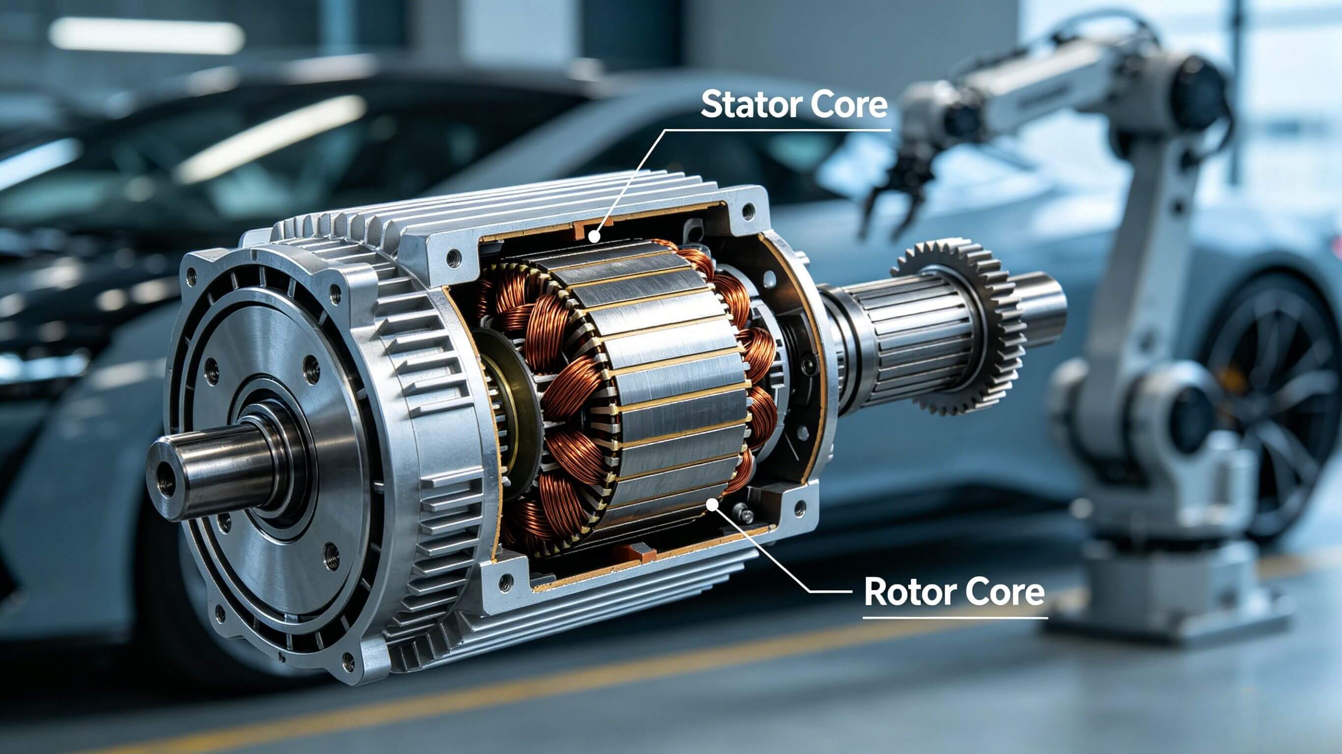
The Changing Anatomy of Scrap Metal The traditional scrap metal mix is evolving rapidly. As global automakers transition from internal combustion engines to electric vehicles (EVs), the materials entering recycling yards and processing facilities are shifting dramatically. Heavy cast iron engine blocks are actively being replaced by lightweight aluminum battery housings, electric motor casings, and complex, high-strength steel structural frames. For scrap yard operators and metal brokers, this new composition presents both a highly lucrative market opportunity and a severe operational challenge. Standard, legacy processing equipment is often highly inefficient—or entirely incapable—of handling these modern, specialized automotive materials.

Maximizing Aluminum Yield in a Lightweight Era The global surge in EV production has led to a massive increase in aluminum CNC machining across the automotive supply chain. This manufacturing process generates hundreds of tons of loose, wet aluminum swarf and turnings. As industry experts know, smelting loose aluminum chips is highly inefficient due to severe surface oxidation, which can result in a devastating 20% to 30% material loss in the furnace.

To capitalize on the high market value of automotive-grade aluminum, recycling facilities must process this specific waste using a high-pressure metal briquetting machine. By compressing the loose, chaotic swarf into ultra-dense, solid cylindrical blocks, facilities prevent metal oxidation during the melting process, effectively maximizing their overall metallurgical yield. Furthermore, the extreme hydraulic pressure extracts valuable cutting fluids, allowing the oils to be recovered and ensuring the briquettes meet the strict, smoke-free environmental standards demanded by modern foundries.

Conquering Advanced High-Strength Steel (AHSS) While EVs utilize significantly more lightweight non-ferrous metals, their core safety frames rely heavily on Advanced High-Strength Steel (AHSS). This specific material is exceptionally tough, highly resistant to deformation, and designed specifically to protect heavy lithium-ion battery packs during severe collisions.

When these modern vehicles or manufacturing offcuts reach the scrap yard, legacy cutting equipment simply lacks the power to process them efficiently, leading to rapidly dulled blades, stalled motors, and costly downtime. Upgrading to a heavy-duty industrial scrap metal shear is no longer an optional upgrade; it is an operational necessity. A modern, robust gantry shear delivers the immense, concentrated hydraulic force required to cleanly slice through AHSS automotive frames without continuous breakdowns, ensuring your yard maintains high-speed, continuous throughput regardless of the vehicle's structural integrity.


Future-Proofing Your Facility
Adapting to the EV revolution is critical for the survival and growth of any modern metal recycling plant. By strategically investing in the right high-pressure and high-force processing equipment today, operators can transform challenging new waste streams into premium, highly profitable commodities.

The Inner Workings of Stone Polishing Machines A Deep Dive into Their Principles

Stone polishing is a meticulous process that begins with the use of abrasive particles. These particles, ranging from coarse to fine, work their magic on the stone surface. Starting with the coarse ones, they gradually reduce the saw marks from previous cutting processes. For instance, in the rough - grinding stage, 50# - 300# diamond grinding blocks are used to clear the initial saw marks and improve the surface flatness.

As we move through the semi - fine grinding, fine grinding, and then to the precision - focused fine - grinding and polishing stages, the scratches become finer and finer until they're almost invisible. When the surface reaches a smoothness of about 110 microns deep, a beautiful mirror - like sheen emerges. Each stage plays a crucial role. Fine grinding reveals the natural patterns of the stone, making it look more vivid, while the polishing stage, with the help of special pads like animal - hair pads or nano - pads and polishing agents, can boost the gloss level to over 85 degrees, sometimes even reaching 90 - 100 degrees.


Physicochemical Principle
Stone polishing is not about using machines to grind the stone. When we polish stone, something important happens, especially when we go back and forth between polishing with water and without water. The stone and the polish we use have a kind of reaction. For example marble is a type of stone that has calcium carbonate in it. When marble meets the parts of the polish like fluosilicic acid or special silica polishes it makes a strong and shiny layer on the stone. This layer does two things for the stone. It makes the stone look really glossy. It helps the stone resist stains. So it is like we are putting a protective and shiny shield on the surface of the stone. Stone polishing and the special layer it makes are really good, for the stone. The. The polish work together to make the stone look great and last a long time.
Key Equipment Characteristics
Modern Stone Polishing Machines, those made for marble have some really cool features. The dual speed system is great because it lets you switch easily between using a lot of power to grind and going really fast to polish. These Modern Stone Polishing Machines are pretty heavy they weigh 250 kilograms and the grinding disc can handle a lot of pressure over 180 kilograms so you know it can grind really well.The grinding disc on these Modern Stone Polishing Machines can be sizes, like 4 inches, 8 inches and 10 inches and you can attach grinding blocks in different ways, which makes these Modern Stone Polishing Machines good for many tasks.Safety is very important so these Modern Stone Polishing Machines have things like voltage, protection, from leaks and a special spring to absorb shocks. Some nice Modern Stone Polishing Machines even have things that make them very easy to use, like adjusting the pressure automatically a laser to help you position things and a system to spray polishing liquid.
Influential Factors
The final polishing effect is affected by several factors. The mineral composition of the stone matters a lot. Stones with clay minerals or a loose structure, like the white - sand beige marble, find it difficult to achieve a high gloss. The type of polishing agent used also plays a crucial role. Dry polishing requires a high - concentration polishing agent, while wet polishing needs careful water - volume control. Additionally, the process parameters, such as pressure, rotation speed, and the compatibility of the grinding disc material, all directly impact the final gloss level.

In conclusion, Stone Polishing Machines, whether they're Granite Polishing Equipment or Marble Grinder and Polishers, use a combination of mechanical grinding and chemical enhancement to bring out the best in our precious stones. It's this intricate balance that gives stones their stunning, high - gloss finish.


2026 Lithium Battery Manufacturing Trends Equipment Upgrade Roadmap

As the global lithium battery industry enters 2026, it is becoming increasingly clear that manufacturing capability—not laboratory-level electrochemical breakthroughs alone—will determine which technologies succeed at scale. Over the past decade, lithium-ion battery performance improvements were primarily driven by materials innovation: higher-nickel cathodes, silicon-doped anodes, improved electrolytes, and optimized additives. However, as energy density gains begin to slow and safety, cost, and sustainability pressures intensify, the industry’s center of gravity is shifting. From my perspective as a manufacturing engineer and system integrator with more than 23 years of experience, the next phase of competition will be defined by equipment architecture, process stability, and factory-level scalability. Technologies such as dry electrode processing and solid-state batteries are often discussed in terms of materials science, yet their real barriers lie in manufacturability. Without corresponding upgrades in production equipment and process control, these technologies cannot move beyond pilot-scale demonstrations.

This article analyzes the 2026 lithium battery manufacturing technology trends from an equipment and process engineering standpoint. It focuses on how dry electrode and solid-state battery technologies are reshaping production line requirements, and it provides a practical equipment upgrade roadmap for manufacturers planning their next-generation factories.

Lithium Battery Manufacturing Trends

Why Equipment Upgrades Are Now the Critical Bottleneck

In traditional lithium-ion battery production, the industry has achieved a relatively mature balance between materials, process parameters, and equipment reliability. Conventional wet-process electrode manufacturing, liquid electrolyte filling, and formation protocols are well understood, and yield optimization follows established methodologies.

However, emerging battery technologies disrupt this balance in three fundamental ways:

1. Process windows become narrower – New materials and structures are less tolerant of variation.

2. Legacy equipment reaches physical limits – Machines designed for slurry-based coating or liquid electrolytes cannot be easily adapted.

3. Scale-up risks increase exponentially – Laboratory success does not translate linearly into mass production.

As a result, equipment design is no longer a downstream consideration. It must be co-developed with the battery technology itself, particularly for dry electrode and solid-state systems.


Dry Electrode Technology: Redefining Electrode Manufacturing Equipment

1. From Slurry Coating to Solid-State Film Forming

Dry electrode technology eliminates solvents and slurry mixing, replacing them with powder-based compaction, fibrillation, and film forming processes. While this approach offers clear advantages—lower energy consumption, reduced environmental impact, and shorter production cycles—it fundamentally changes equipment requirements.

Traditional coating lines rely on: - Slurry mixing systems - Slot-die or comma coaters - Long drying ovens - Solvent recovery units

Dry electrode lines, by contrast, require: - High-precision powder feeding systems - Controlled fibrillation or binder activation mechanisms - High-pressure calendering and film densification equipment - Inline thickness and density monitoring

2. New Equipment Challenges

From an engineering standpoint, dry electrode processing introduces several non-trivial challenges:

• Powder uniformity control: Unlike liquids, powders exhibit segregation, agglomeration, and flow instability.

• Mechanical stress management: Excessive compaction can damage active materials or conductive networks.

• Process repeatability: Small variations in pressure or temperature can lead to large performance deviations.

At TOB New Energy, our engineering teams have observed that many early dry electrode pilot lines fail not because of material chemistry, but because equipment lacks sufficient process control resolution.


Solid-State Batteries: Equipment Must Enable Interfaces, Not Just Assembly

1. The Manufacturing Reality of Solid-State Cells

Solid-state batteries promise improved safety and potentially higher energy density, yet they also impose unprecedented demands on manufacturing equipment. Unlike liquid electrolyte systems, solid-state cells are interface-dominated systems. The quality of contact between solid electrolyte and electrodes determines ionic conductivity, cycle life, and reliability.

This shifts the role of equipment from simple assembly to interface engineering.

2. Key Equipment Requirements for Solid-State Production

Solid-state battery manufacturing requires equipment capable of:

• High-precision layer stacking and alignment

• Uniform pressure application during lamination

• Controlled atmosphere handling for moisture-sensitive materials

• Low-damage densification and sintering processes (where applicable)

Many existing lithium-ion assembly machines cannot meet these requirements without substantial redesign. For example, standard lamination equipment may lack the pressure uniformity or feedback control needed for solid electrolyte layers.

solid state battery


Traditional vs. New-Generation Manufacturing Processes

The following table summarizes the key differences between conventional lithium-ion battery manufacturing and emerging dry electrode and solid-state processes from an equipment perspective.

Dimension

Traditional Lithium-Ion Process

Dry Electrode Process

Solid-State Battery Process

Electrode Preparation

Slurry mixing + wet coating

Powder-based film forming

Solid or composite layer forming

Drying Requirement

Long solvent drying ovens

No solvent drying

Limited or no drying

Key Equipment Bottleneck

Coating uniformity, drying efficiency

Powder handling, calendering control

Interface pressure & alignment

Process Sensitivity

Moderate

High

Very high

Equipment Customization Level

Low–medium

High

Very high

Scale-Up Difficulty

Relatively mature

Medium–high

High

This comparison highlights a critical point: new battery technologies demand disproportionately higher equipment sophistication, even when overall process steps appear simpler.


Equipment Upgrade Roadmap for 2026–2028

Based on our internal projects and customer collaborations, TOB New Energy recommends a phased equipment upgrade strategy rather than abrupt technology replacement.

Phase 1: Hybrid Lines and Modular Upgrades

Manufacturers should begin with hybrid production lines that retain proven downstream processes (assembly, formation, aging) while selectively upgrading upstream equipment such as:

• Dry electrode pilot modules

• Advanced calendering systems with closed-loop control

• Enhanced metrology and inline inspection

This approach reduces capital risk while allowing teams to accumulate process data.


Phase 2: Dedicated Pilot Lines

Once process stability is demonstrated, dedicated pilot lines should be deployed with:

• Fully customized electrode fabrication equipment

• Solid-state compatible lamination and stacking systems

• Expanded environmental control (humidity, particulate levels)

At this stage, the focus shifts from feasibility to yield optimization and reproducibility.


Phase 3: Mass Production Line Engineering

For full-scale deployment, equipment design must prioritize:

• Long-term mechanical stability

• Maintainability and spare part standardization

• Integration with MES and quality traceability systems

In our experience, many scale-up failures occur because pilot-line equipment is directly copied into mass production without redesign for continuous operation.


Expert Insight: TOB Engineers’ View on Future Capacity

According to internal projections by TOB New Energy’s engineering team, by 2030, more than 30% of newly built lithium battery production capacity will incorporate dry electrode or solid-state–compatible equipment architectures.

However, this does not imply an immediate replacement of conventional lines. Instead, we expect a prolonged period of coexistence, where traditional wet processes dominate high-volume applications, while advanced equipment-enabled technologies serve high-performance, safety-critical, or sustainability-driven markets.

Our engineers also anticipate that equipment suppliers capable of customization, rapid iteration, and cross-technology integration will play a decisive role in enabling this transition.


Conclusion: Manufacturing Capability as Strategic Advantage

As we look beyond 2026, it is evident that the lithium battery industry is entering a manufacturing-driven era. Dry electrode and solid-state technologies will not succeed solely on the basis of materials innovation. Their success depends on whether equipment systems can deliver process stability, scalability, and economic viability.

For battery manufacturers, the key strategic question is no longer “Which chemistry is best?” but rather “Which technology can we manufacture reliably at scale?” The answer to this question will be shaped by equipment upgrade decisions made today.

At TOB New Energy, we believe that engineering depth, customization capability, and real-world factory experience are essential to navigating this transition. By aligning technology ambition with manufacturing reality, the industry can move from promising concepts to sustainable, large-scale energy storage solutions.

Dry Electrode Process The Key to Mass Production of High-Performance Solid-State Battery

In all-solid-state batteries, the liquid electrolyte is replaced by a solid-state electrolyte membrane. Consequently, the front-end production process requires the preparation of this solid electrolyte film in addition to the traditional positive and negative electrode sheets. This process is a critical link in the battery manufacturing workflow, directly determining the performance and quality of the final cell. While the wet process currently dominates solid-state battery production lines, the dry process is increasingly becoming the mainstream direction for next-generation solid-state battery front-end technology, thanks to its combined advantages in cost, process efficiency, and material compatibility.


01. Key Upgrades in Solid-State Battery Pre-Forming Production

The manufacturing process for solid-state batteries fundamentally differs from that of traditional liquid batteries. The front-end film preparation segment is the critical, transitional phase in the battery manufacturing process. This stage directly dictates the finished cell's energy density, rate performance, and cycle life. In all-solid-state batteries, the solid-state electrolyte membrane replaces the liquid electrolyte. Therefore, front-end preparation must include not only the conventional positive and negative electrode sheets but also the solid-state electrolyte film. This fundamental change introduces new challenges and simultaneously presents opportunities for process upgrading.

dry electrode sheet

02. Technological Transformation: The Leap from Wet to Dry Process

Current solid-state battery front-end preparation processes are mainly categorized into two technical routes: wet and dry. The wet process still relies on the solvent system of traditional liquid batteries, where electrode or electrolyte materials are mixed with a binder to form a slurry, coated, and then dried to complete film formation.

While this process is relatively mature, it has inherent drawbacks: it requires the use of large amounts of toxic organic solvents (such as NMP), necessitates high-energy-consumption steps for drying and solvent recovery, and restricts the application of certain cutting-edge materials sensitive to solvents.

In contrast, the dry process innovates electrode manufacturing by eliminating the use of solvents and the subsequent drying step. The dry process relies more heavily on high-shear dry mixing and fibrillation equipment to achieve uniform material dispersion and pre-forming, followed by multi-roll pressing to complete the film formation directly.


The core advantages of dry film formation technology are evident across three dimensions:

• Cost Efficiency: By omitting the coating, drying, and solvent recovery stages, equipment investment is lower, energy consumption is reduced, and overall cell manufacturing costs can be reduced by approximately 18%.

• Performance Enhancement: The dry process effectively increases the active material's compaction density, leading to an energy density increase of about 20%. SAIC Group's semi-solid-state battery, integrated into its MG4 model, has achieved a system energy density of 400Wh/kg, supporting a 12-minute fast charge for 400 km.

• Environmental and Material Compatibility: The dry process eliminates the need for toxic solvents, solving the environmental pollution issues of the traditional wet process. Concurrently, it enables the application of more cost-effective materials (such as manganese-based cathodes).


03. Technology Matrix: Diversified Paths for Dry Film Formation

Dry film formation is not a single process but a matrix encompassing various technical routes. Currently, the more representative dry electrode preparation technologies primarily include six types:

• Fibrillation Method: Uses high shear force to fibrillate the binder, enabling it to tightly encapsulate active materials and conductive agents, forming a self-supporting electrode film. This process demands extremely high shear force and temperature control capabilities from the equipment.

• Dry Spray Deposition: Utilizes charged powder, which is uniformly deposited onto the current collector under an electric field, followed by hot pressing to melt and fix the binder, forming a self-supporting film.

• Other Methods: Vapor deposition, hot-melt extrusion, direct pressing, and 3D printing are applied based on different material characteristics and application scenarios.

These different paths vary in technical principles, applicable materials, film-forming capability, and equipment complexity, and are suited for different applications such as large-scale, flexible electrodes, small-sized devices, and thick electrode sheets.


Comparison of Major Dry Film Formation Technical Routes

Technical Route

Core Principle

Applicable Scenarios

Equipment Complexity

Fibrillation Method

High shear force fibrillates binder to wrap active material

Large electrodes, all-solid-state batteries

High

Dry Spray Deposition

Electrostatic powder deposition followed by hot pressing

Flexible electrodes, complex shapes

Medium

Direct Pressing

Direct pressing and forming of powder material

Thick electrode sheets, experimental lines

Low

3D Printing

Layer-by-layer accumulation and forming

Small-sized devices, customized structures

High

The industry generally considers the Binder Fibrillation Method to exhibit superior performance stability and processability, positioning it as the emerging mainstream route.


04. Industrialization Challenges: Bridging the Gap from Laboratory to Mass Production

Despite the clear advantages of dry film formation, scaling from the laboratory to mass production faces numerous hurdles. Capacity and efficiency are paramount concerns. Dry coating capacity and speed still lag behind traditional wet processes, and uniformity and adhesion performance during wide-format spraying require significant improvement.

Coating uniformity and quality control present another major challenge. Non-uniform dry electrode coatings can create "hot spots" within the electrode, leading to accelerated battery performance degradation and potential safety risks.

Binder and material compatibility also need further optimization. Achieving uniform distribution of PTFE fibrils within the mixture while preventing damage to active material particles is essential. Furthermore, PTFE is unstable at low potentials and reacts irreversibly with lithium, which limits its application in negative electrodes.

Challenges on the equipment side are equally severe. The dry process imposes higher demands on core roller-pressing machinery. The performance and production efficiency of the calendaring machine as the core equipment are central to determining the dry process's viability for mass production.

TOB NEW ENERGY is actively working to address these challenges, aiming to control the binder content in the negative electrode to 0.7% and the positive electrode below 1.5% to achieve more efficient, low-cost film-forming performance.


05. Equipment Innovation: The Critical Force Driving Dry Process Implementation

Equipment typically spearheads the industrialization of solid-state batteries. In the realm of dry film formation, equipment innovation is the key driver for technological implementation.

• Front-End Process Equipment: Accounts for approximately 32% of the entire production line's value, including core equipment for high-efficiency mixing, material dispersion, coating, and high-shear treatment.

• Mid-End Process Equipment: Accounts for approximately 45% of the line's value, centered around high-efficiency stacking machine (25% of the line's value) and horizontal isostatic presses (13% of the line's value), covering the entire process from shaping to densification.

• Back-End Process Equipment: Accounts for approximately 23% of the line's value, including dry powder comprehensive testers and horizontal high-temperature fixture solutions for solid-state battery integrated cabinets, achieving high-voltage formation and capacity grading and assembly.


06. TOB NEW ENERGY: Providing Comprehensive Solutions from Laboratory to Mass Production

Addressing the industrialization opportunities and challenges of dry film formation technology, TOB NEW ENERGY leverages years of technical accumulation in battery manufacturing to offer customers a complete solution spanning from the laboratory to mass production.

Solutions for Laboratory-Scale Dry Electrode Lines

We provide a full suite of customized equipment and services for dry electrode experimental lines. Our developed Laboratory Jet Mill integrates miniaturization, intelligence, and high precision, suitable for experimental-grade powder preparation needed for the fibrillation of lithium battery dry electrode materials. The Lab Dry Electrode Film Forming Machine is a laboratory dry electrode research equipment that can be used for the powder to film forming process.

Laboratory Jet Mill

Lab Dry Electrode Film Forming Machine

Solutions for Pilot-Scale Production

We offer Dry Electrode Film Forming Machines that support various production line requirements, including equipment for GWh-level mass production capacity. Through precise tension control and thickness adjustment, we can achieve the preparation of dry electrode sheets as thin as 27μm or even thinner.

Dry Electrode Film Forming Machines

Solutions for Industrial Mass Production

For industrial mass production needs, we provide complete dry electrode production line solutions. Our system covers all processes, including controllable feeding, film formation, thinning, current collector compounding, and quality inspection. Product width can reach 1000mm, with a thickness range of 40-300μm, and is compatible with 2 to 6 dry electrode sheets operating in parallel for high-efficiency production.


Our technical team deeply understands every aspect of the dry film formation process and can provide customized process optimization solutions based on the client’s specific material systems (such as graphite/silicon-carbon negative electrodes, ternary/LFP positive electrodes, and various all-solid-state electrode materials) and equipment needs. On the materials front, we support our clients with cutting-edge battery materials, including specialized binders and modified conductive agents suitable for the dry process, ensuring optimal compatibility between materials and process.


Formation and Grading in Lithium-Ion Battery Manufacturing

Formation and capacity grading are among the final and most critical stages in lithium-ion battery manufacturing. Although these steps occur after electrode fabrication and cell assembly, they strongly influence the electrochemical stability, safety performance, consistency, and lifetime of the final product. In industrial battery production lines, the formation process activates the battery for the first time, while the grading process evaluates and classifies the cells based on measurable electrical parameters.

From an engineering perspective, these operations are not simple charging and testing procedures. Each step — electrolyte filling, aging, formation, secondary filling, K-value evaluation, and capacity grading — is designed based on electrochemical mechanisms, mass transport behavior, gas evolution, and quality control requirements. In modern battery factories, the design of these processes must be integrated with the overall production line layout, equipment capability, and target performance specifications. For manufacturers building new facilities, these steps are typically implemented as part of a complete lithium battery production line solution, where formation systems, aging rooms, and grading machines are configured according to capacity and chemistry requirements.

This article provides a detailed engineering explanation of each step in the formation and capacity grading process, together with the physical and chemical reasons behind the operations.
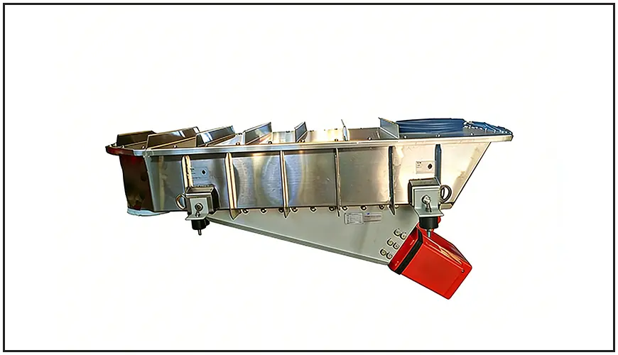

battery formation and grading system


1. First Electrolyte Filling After Cell Assembly


After the electrode stack or jelly-roll is inserted into the cell casing, the first electrolyte filling operation must be performed. In industrial terminology, this step is calledfirst filling, because a second filling will be required later in the process.

During the first filling, the assembled cell is placed in a vacuum filling chamber. The chamber is evacuated to create negative pressure inside the cell. Once the internal pressure is sufficiently low, the electrolyte valve is opened, and the electrolyte flows into the cell due to the pressure difference. This method ensures that the electrolyte penetrates into the separator pores and electrode structure more efficiently than simple atmospheric filling.

The purpose of the first filling is not only to introduce electrolyte, but also to ensure uniform wetting of porous electrodes. Poor wetting can lead to high internal resistance, non-uniform SEI formation, and capacity loss in later stages.


2. High-Temperature Aging for Electrolyte Wetting


Cells cannot be charged immediately after the first filling. Anyone who has worked with coin cells or laboratory cells knows that newly assembled batteries must rest for a period of time to allow the electrolyte to fully soak into the electrodes. In industrial production, this step is performed ashigh-temperature aging.

The cells are placed in a controlled high-temperature aging room for a specified period to accelerate electrolyte diffusion into the electrode pores. Proper wetting is essential for stable SEI formation during the subsequent formation process.

During aging, the cell is not yet permanently sealed. Therefore, a temporary sealing pin must be used to close the filling port. Without temporary sealing, high temperature may cause electrolyte evaporation, leading to concentration change, performance instability, and potential safety hazards.


Table 1 — Purpose of High-Temperature Aging

Parameter

Engineering Purpose

Effect on Battery

Elevated temperature

Increase electrolyte diffusion rate

Improves wetting uniformity

Rest time control

Ensure full penetration of electrodes

Reduces formation defects

Temporary sealing

Prevent electrolyte evaporation

Maintains electrolyte composition

Controlled environment

Avoid contamination

Improves consistency


battery formation system


3. Formation Process and SEI Film Generation


After aging, the cells enter theformation process, which is the first electrochemical activation of the battery. The main objective of formation is to create a stablesolid electrolyte interphase (SEI)on the surface of the negative electrode.

During the first charge, the electrolyte decomposes at the graphite surface, forming a thin but dense SEI layer. This layer allows lithium ions to pass while preventing further electrolyte decomposition. The quality of the SEI film directly determines cycle life, internal resistance, and safety.

To obtain a high-quality SEI film, formation is usually performed using a multi-step current profile.

Step

Current Level

Purpose

Initial charge

Low current

Form dense SEI layer

Intermediate charge

Moderate current

Stabilize interface

Final charge

Higher current

Adapt to real working condition

Rest / discharge

Controlled

Check stability


Gas generation occurs during formation because electrolyte decomposition produces gases such as CO₂and hydrocarbons. To avoid gas accumulation at the electrode interface, industrial production often usesnegative-pressure formation, where gas is removed during the process.

Gas trapped between electrode layers can block lithium-ion transport paths, leading to non-uniform SEI formation and performance variation between cells.

In modern factories, formation systems are designed together with the
battery formation and grading equipment, ensuring precise current control, temperature stability, and gas management.


4. Secondary Electrolyte Filling


After formation, the cell undergoessecond electrolyte filling.

Two main reasons require this step:

- SEI formation consumes part of the electrolyte
- Negative-pressure formation removes some electrolyte together with gas

As a result, the electrolyte amount inside the cell becomes lower than the designed value. Secondary filling compensates for the loss and ensures correct electrolyte volume.

The operation is similar to the first filling, but the filling quantity is smaller. After the second filling, the filling port is welded to permanently seal the cell.


Table 2 — Comparison of First and Second Filling

Item

First Filling

Second Filling

Purpose

Initial wetting

Electrolyte compensation

Electrolyte volume

Full amount

Partial amount

Timing

After assembly

After formation

Sealing status

Temporary

Permanent after filling


5. OCV Measurement and High-Temperature K-Value Test


After sealing, the cell must undergotwo open-circuit voltage (OCV) measurementsbefore capacity grading.

The purpose is to calculate thehigh-temperature K-value, which describes the self-discharge rate of the battery.

The formula is:

K = (OCV1−OCV2) / (T2−T1)

Unit: mV/h

The cell is stored at elevated temperature between the two measurements. A large K-value indicates abnormal voltage drop, which may be caused by internal leakage, contamination, or micro-short circuits.

Cells with excessive K-value must be removed before grading.

Table 3 — Interpretation of High-Temperature K-Value

K-Value Level

Possible Cause

Action

Low

Normal self-discharge

Accept

Medium

Minor impurity

Monitor

High

Micro short circuit

Reject

Very high

Internal defect

Scrap


6. Capacity Grading (Formation Test Cycling)


Capacity grading is the process of charging and discharging the cell to measure capacity, internal resistance, and efficiency.

In industrial production, grading is usually performed at relatively high current (0.5C–1C) to simulate actual operating conditions.

Cells are then sorted into different grades according to measured capacity.

Example classification:

Grade

Capacity Range

Application

A

Highest capacity

High-performance pack

B

Standard

Normal products

C

Lower capacity

Secondary use

Reject

Out of spec

Scrap

Grading machines must provide accurate current control, temperature management, and high channel consistency, which is why they are normally integrated into a
battery pilot line or production line solution rather than used as standalone equipment.


7. Room-Temperature K-Value Test After Depolarization


After grading, the cells cannot be tested immediately again. The battery must rest at room temperature to allowdepolarization.

Right after charge and discharge, the voltage drops quickly due to relaxation of the electrode potential. If OCV is measured immediately, the calculated K-value will be artificially high.

Therefore, cells are stored for a period until voltage becomes stable, then a second K-value test is performed at room temperature.

This test further removes defective cells before shipment.


8. Final Release of Qualified Cells


After completing:

- First filling

- Aging

- Formation

- Second filling

- High-temperature K test

- Capacity grading

- Room-temperature K test

the cells can be released from the factory.

Although these steps occur at the end of the process, they determine whether the battery will meet its design specifications. Incomplete formation, poor wetting, insufficient electrolyte, or inaccurate grading will directly reduce cycle life and consistency.
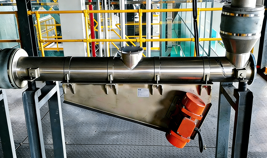
For this reason, the formation and grading section is often the most power-consuming, time-consuming, and equipment-intensive part of a battery factory, and must be considered at the early stage of plant design.


About TOB NEW ENERGY


TOB NEW ENERGY is a global one-stop solution provider for battery manufacturing, covering laboratory research lines, pilot lines, and full-scale production lines. The company provides factory planning, equipment manufacturing, process integration, installation, commissioning, and technical training for lithium-ion, sodium-ion, solid-state, and next-generation battery technologies.

Learn more about complete solutions: TOB NEW ENERGY Battery Production Solutions

How to Solve Electrode Slurry Sedimentation and Agglomeration

Electrode slurry preparation is one of the most critical yet underestimated steps in lithium-ion and sodium-ion battery manufacturing. Problems such as particle sedimentation, agglomeration, poor dispersion uniformity, and unstable viscosity often originate at the slurry stage, but their consequences propagate downstream into coating defects, capacity inconsistency, and yield loss.

This article systematically explains why slurry sedimentation and agglomeration occurhow key process parameters such as mixing speed and vacuum level influence slurry quality, and how to select a suitable vacuum mixer from an engineering perspective. The content is written for battery manufacturers, R&D centers, and pilot-line engineers seeking stable, scalable, and reproducible slurry preparation.

Electrode Slurry


1. Why Do Electrode Slurries Sediment and Agglomerate During Mixing?

1.1 Sedimentation Caused by Density Differences and Insufficient Shear

Electrode slurries consist of high-density solid materials (active materials, conductive additives) dispersed in relatively low-density liquid phases (NMP or water-based solvents). Typical cathode and anode powders-such as NCM, LFP, graphite, silicon–graphite composites, or hard carbon-have densities several times higher than the solvent system.

If the shear force generated during mixing is insufficient, gravitational forces dominate over suspension forces, causing heavier particles to gradually settle. This phenomenon becomes more severe under the following conditions:

  • High solid loading formulations (>50–60 wt%)
  • Large batch volumes with limited flow circulation
  • Long dwell times between process steps

Sedimentation leads to vertical composition gradients in the slurry. The bottom layer becomes over-concentrated with solids, while the upper layer becomes binder- and solvent-rich. Once such gradients form, they are difficult to eliminate and directly affect coating thickness uniformity, electrode density, and electrochemical consistency.


1.2 Agglomeration Driven by Surface Energy and Binder Bridging

Agglomeration originates from the high surface energy of fine powders. Nano- or micron-scale particles tend to cluster together to minimize total surface energy. In battery slurries, this natural tendency is amplified by process-related factors.

Common causes include:

  • Rapid powder feeding without sufficient pre-wetting
  • Binder added too early, forming localized polymer bridges
  • Inadequate shear stress to break initial clusters

Once agglomerates form, they behave as large pseudo-particles that are resistant to dispersion. These hard clusters often survive the entire mixing process and later appear as pinholes, streaks, or localized resistance anomalies in coated electrodes.


1.3 Air Entrapment as a Hidden Root Cause

Air introduced during powder addition or high-speed atmospheric mixing becomes trapped inside particle clusters. These air pockets prevent solvent penetration and block effective wetting of internal particle surfaces.

Without degassing, trapped air stabilizes agglomerates and worsens sedimentation behavior. This is why slurries mixed under atmospheric conditions often show acceptable appearance initially but degrade rapidly during storage or transfer.


2. How Do Mixing Speed and Vacuum Level Affect Slurry Fineness and Stability?

2.1 Mixing Speed: Controlling Shear and Dispersion Efficiency

Mixing speed directly determines the magnitude of shear stress applied to particle clusters. As rotational speed increases:

  • Agglomerates experience stronger mechanical forces
  • Binder and conductive additives distribute more uniformly
  • Solid–liquid contact efficiency improves

However, increasing speed alone has limitations. Excessive speed under atmospheric conditions can introduce new air, raise slurry temperature, and accelerate binder degradation. Therefore, mixing speed must be optimized rather than maximized.


2.2 Vacuum Level: Enhancing Wetting and Degassing

Vacuum fundamentally changes slurry behavior. Under reduced pressure, entrapped air expands and escapes from the slurry, allowing solvent to penetrate particle clusters more effectively.

At high vacuum levels (typically −0.08 to −0.095 MPa):

  • Air bubbles are rapidly removed
  • Powder wetting becomes more complete
  • Binder penetrates micro-pores within agglomerates

This results in finer dispersion, lower apparent viscosity fluctuation, and improved long-term slurry stability.


2.3 Synergistic Effect of Speed and Vacuum

Engineering data consistently show that:

  • Increasing speed alone improves fineness but quickly reaches a plateau
  • Vacuum alone improves wetting but requires shear to break clusters
  • Vacuum combined with appropriate speed delivers the best dispersion efficiency

In practice, vacuum acts as a multiplier for shear effectiveness, enabling high-quality dispersion without excessive mechanical stress.


3. How to Select the Right Vacuum Mixer for Electrode Slurry Preparation?

3.1 Limitations of Conventional Atmospheric Mixers

Traditional planetary or paddle mixers operating at atmospheric pressure are limited by:

  • Incomplete air removal
  • Poor repeatability at high solid loadings
  • Long mixing cycles with inconsistent results

These limitations become critical when scaling from laboratory formulations to pilot and mass production.


3.2 Key Equipment Features Required for Stable Slurry Production

A vacuum mixer designed for battery electrode slurries should meet the following engineering requirements:

Equipment Feature Engineering Advantage Practical Application
High-stability vacuum system Efficient removal of entrapped air and dissolved gases Prevents agglomeration and viscosity fluctuation
Variable speed control Enables staged mixing from wetting to dispersion Improves reproducibility across batches
High torque output Handles high-viscosity and high-solid slurries Suitable for high-energy-density formulations
Uniform mixing geometry Eliminates dead zones and local concentration gradients Ensures coating consistency
Temperature control (optional) Prevents binder degradation and solvent loss Critical for long mixing cycles


3.3 Typical Application Scenarios

Vacuum mixers are widely used in:

  • High-energy-density cathode slurry preparation (NCM, NCA)
  • High-viscosity silicon–graphite anode systems
  • Sodium-ion battery electrode development
  • R&D and pilot lines requiring high formulation repeatability

In production environments, vacuum mixers enable process standardization, which is essential for yield control, scale-up, and quality assurance.


Conclusion

Sedimentation and agglomeration in electrode slurries are not random defects but predictable physical phenomena driven by density differences, surface energy, and air entrapment.

From an engineering perspective:

  • Mixing speed controls shear force
  • Vacuum level controls wetting and degassing efficiency
  • Proper vacuum mixer selection allows both factors to work synergistically

By understanding these mechanisms and selecting appropriate equipment, battery manufacturers can achieve stable, reproducible, and scalable slurry preparation-laying a solid foundation for high-quality electrode production.


About TOB NEW ENERGY
TOB NEW ENERGY is a one-stop solution provider for battery laboratory lines, pilot lines, and mass production lines. With deep expertise in electrode slurry preparation, mixing process design, and customized battery equipment, TOB supports global battery manufacturers, research institutes, and universities in building stable, scalable, and reproducible electrode manufacturing systems.
Learn more about TOB NEW ENERGY’s battery equipment and engineering solutions

Lithium Battery Laboratory Setup Checklist (2026 Edition)

Introduction: Why Battery Laboratory Design Matters More Than Ever in 2026

In 2026, lithium battery laboratories are no longer isolated research spaces dedicated only to material discovery. They have become critical engineering bridges between fundamental electrochemistry and industrial-scale manufacturing.

Over the past five years, battery innovation cycles have shortened significantly. New chemistries-such as sodium-ion systems, high-silicon anodes, solid-state electrolytes, and dry electrode processes-are now expected to move from laboratory validation to pilot-scale demonstration within 18–36 months.

As a result, laboratory infrastructure must meet three simultaneous requirements:

● Support high-variability experimental research

● Maintain process consistency and reproducibility

● Enable direct transfer to pilot and mass production environments

This 2026 laboratory checklist is structured to reflect these realities. Rather than listing equipment randomly, it organizes laboratory construction around budget tiers, cell formats, and engineering objectives, ensuring that every investment contributes to long-term scalability.


Coin cell lab line


I. Low-Budget Laboratory Setup

Positioning: Fundamental research and feasibility validation

 1. Core Infrastructure (All Cell Types)

Equipment

Function

Engineering Advantages

Typical Applications

Manual Glove Box

Provides inert atmosphere (≤1 ppm H₂O/O₂)

Prevents material degradation and parasitic reactions

Electrode handling, slurry prep, cell assembly

Analytical Balance (0.1 mg)

Precise mass measurement

Ensures accurate electrode loading

Material formulation, electrolyte dosing

Vacuum Drying Oven

Removes residual moisture

Improves electrochemical stability

Electrode, separator, material drying

Laboratory Fume Hood

Solvent vapor extraction

Enhances operator safety

Slurry preparation, electrolyte handling

Deionized Water System

Supplies high-purity water

Prevents ionic contamination

Cleaning, material processing


2. Coin Cell Laboratory (CR20xx)

Equipment

Function

Advantages

Engineering Use

Manual Coin Cell Crimper

Seals coin cells mechanically

Simple, reliable, low cost

Material screening, baseline electrochemistry

Disc Cutter

Cuts electrodes/separators

Uniform geometry, reduced variability

Reproducible coin cell assembly

Manual Slurry Mixer

Mixes active materials and binders

Flexible formulation testing

Cathode/anode development

Manual Coating Applicator

Applies slurry to foil

Fast iteration, adjustable thickness

Small-batch electrode trials

Compact Roll Press

Densifies electrodes

Improves conductivity and adhesion

Capacity and cycle optimization


3. Cylindrical Cell (18650 / 21700 – Feasibility Level)

Equipment

Function

Advantages

Engineering Use

Manual Slitting Machine

Cuts electrode sheets into strips

Low investment, format flexibility

Small-batch cylindrical trials

Manual Winding Jig

Winds electrodes into cylindrical form

Enables geometry validation

Early cylindrical feasibility

Spot Welding Machine

Connects tabs and leads

Stable electrical connection

Internal resistance control

Manual Electrolyte Filling

Injects electrolyte

Supports chemistry variation

Wetting behavior studies

Small Aging Cabinet

Stores cells under control

Enables initial formation

Short-term stability evaluation


4. Pouch Cell (Single-layer)

Equipment

Function

Advantages

Engineering Use

Manual Stacking Fixture

Aligns electrodes/separators

Improves layer consistency

Prototype pouch validation

Vacuum Sealing Machine

Seals pouch under vacuum

Prevents air/moisture ingress

Leak prevention

Electrolyte Injection Tool

Fills electrolyte accurately

Avoids over/under-filling

Electrochemical consistency


II. Mid-Budget Laboratory Setup

Positioning: Process optimization and pilot validation

1. Infrastructure Upgrade

Equipment

Function

Engineering Advantages

Application

Automatic Glove Box (Dual Station)

Parallel inert processing

Improved efficiency, workflow separation

Medium-throughput R&D

Vacuum Planetary Mixer

Uniform slurry mixing + degassing

Reduces coating defects

Process optimization

Continuous Coating & Drying Unit

Continuous electrode fabrication

Stable thickness and porosity

Scale-up evaluation

Automatic Roll Press

Uniform densification

Reduces batch variability

Performance consistency

Precision Slitter

High-accuracy electrode cutting

Supports multiple formats

Cylindrical & pouch cells


2. Coin Cell (High-Throughput)

Equipment

Function

Advantages

Engineering Role

Automatic Coin Cell Assembler

Automated stacking & crimping

High repeatability

Statistical material screening

Electrolyte Dispensing System

Precise volume control

Reduces operator error

Comparative testing

Barcode Tracking

Sample identification

Full traceability

Data integrity


3. Cylindrical Cell (18650 / 21700 / 32140)

Equipment

Function

Advantages

Engineering Role

Semi-Automatic Winder

Controlled electrode winding

Lower defect rate

Yield evaluation

Laser / Ultrasonic Welding

High-quality tab welding

Stable electrical paths

Resistance control

Controlled Filling System

Accurate electrolyte injection

Improved wetting

Cycle life optimization

Formation & Grading Cabinets

Initial cycling & sorting

Quality differentiation

Process window definition


4. Pouch Cell (Multi-layer)

Equipment

Function

Advantages

Engineering Role

Semi-Automatic Stacker

Multi-layer electrode stacking

Alignment accuracy

Layer consistency

Vacuum Heat Sealer

Multi-edge sealing

Repeatable sealing quality

Reliability improvement

Degassing Station

Removes trapped gas

Enhances cycle life

Long-term stability


III. High-Budget Laboratory / Pilot Facility

Positioning: Direct production transfer


1. Production-Grade Infrastructure

Equipment

Function

Engineering Advantages

Application

Central Slurry System

Large-batch mixing

High uniformity

Pilot-scale coating

Automatic Coating Line

Precision coating

Production-level consistency

Scale validation

Solvent Recovery System

Solvent recycling

Cost and environmental control

Sustainable operation

Roll-to-Roll Calender

Continuous densification

Industrial electrode quality

Manufacturing transfer

MES Data System

Process monitoring

Traceability & optimization

Factory readiness


2. Cylindrical Cell (Pilot Level)

Equipment

Function

Advantages

Engineering Role

High-Speed Winding Machine

Automated winding

High throughput

Production simulation

Inline Welding & Inspection

Real-time defect detection

Yield protection

Quality assurance

Vacuum Filling & Soaking

Improved wetting

Shorter formation

Process efficiency

Automated Formation & Aging

Capacity grading

Consistent quality

Production readiness


3. Pouch Cell Pilot Line

Equipment

Function

Advantages

Engineering Role

Automatic Stacking / Z-Folding

High-precision stacking

Layer repeatability

Pilot production

Inline Sealing Line

Automated pouch forming

Low leakage rate

Reliability validation

Automated Degassing

Gas removal

Safety and lifespan

Quality control

Formation & Aging Warehouse

Large-scale formation

Production simulation

Capacity consistency


4. Advanced Safety & Analysis

Equipment

Function

Engineering Value

Application

High-Power Cyclers

High-current testing

Power capability validation

EV & ESS cells

Abuse Test Chambers

Safety testing

Failure mechanism analysis

Certification prep

CT Scanning System

Internal defect imaging

Root cause analysis

Design optimization


Conclusion

A lithium battery laboratory in 2026 must be designed as a scalable engineering system, not a collection of isolated tools.

From low-budget research labs to pilot-scale facilities, each equipment decision should serve a clear engineering purpose: enabling reliable data, reducing scale-up risk, and accelerating the transition to production.

At TOB NEW ENERGY, laboratory systems are engineered as the first controllable stage of manufacturing, ensuring that innovation can move efficiently from concept to commercialization.