How to Solve Electrode Slurry Sedimentation and Agglomeration

Electrode slurry preparation is one of the most critical yet underestimated steps in lithium-ion and sodium-ion battery manufacturing. Problems such as particle sedimentation, agglomeration, poor dispersion uniformity, and unstable viscosity often originate at the slurry stage, but their consequences propagate downstream into coating defects, capacity inconsistency, and yield loss.

This article systematically explains why slurry sedimentation and agglomeration occurhow key process parameters such as mixing speed and vacuum level influence slurry quality, and how to select a suitable vacuum mixer from an engineering perspective. The content is written for battery manufacturers, R&D centers, and pilot-line engineers seeking stable, scalable, and reproducible slurry preparation.

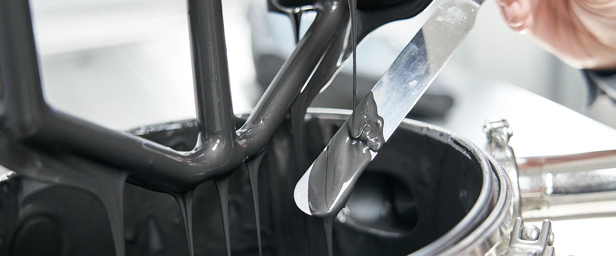
Electrode Slurry


1. Why Do Electrode Slurries Sediment and Agglomerate During Mixing?

1.1 Sedimentation Caused by Density Differences and Insufficient Shear

Electrode slurries consist of high-density solid materials (active materials, conductive additives) dispersed in relatively low-density liquid phases (NMP or water-based solvents). Typical cathode and anode powders-such as NCM, LFP, graphite, silicon–graphite composites, or hard carbon-have densities several times higher than the solvent system.

If the shear force generated during mixing is insufficient, gravitational forces dominate over suspension forces, causing heavier particles to gradually settle. This phenomenon becomes more severe under the following conditions:

  • High solid loading formulations (>50–60 wt%)
  • Large batch volumes with limited flow circulation
  • Long dwell times between process steps

Sedimentation leads to vertical composition gradients in the slurry. The bottom layer becomes over-concentrated with solids, while the upper layer becomes binder- and solvent-rich. Once such gradients form, they are difficult to eliminate and directly affect coating thickness uniformity, electrode density, and electrochemical consistency.


1.2 Agglomeration Driven by Surface Energy and Binder Bridging

Agglomeration originates from the high surface energy of fine powders. Nano- or micron-scale particles tend to cluster together to minimize total surface energy. In battery slurries, this natural tendency is amplified by process-related factors.

Common causes include:

  • Rapid powder feeding without sufficient pre-wetting
  • Binder added too early, forming localized polymer bridges
  • Inadequate shear stress to break initial clusters

Once agglomerates form, they behave as large pseudo-particles that are resistant to dispersion. These hard clusters often survive the entire mixing process and later appear as pinholes, streaks, or localized resistance anomalies in coated electrodes.


1.3 Air Entrapment as a Hidden Root Cause

Air introduced during powder addition or high-speed atmospheric mixing becomes trapped inside particle clusters. These air pockets prevent solvent penetration and block effective wetting of internal particle surfaces.

Without degassing, trapped air stabilizes agglomerates and worsens sedimentation behavior. This is why slurries mixed under atmospheric conditions often show acceptable appearance initially but degrade rapidly during storage or transfer.


2. How Do Mixing Speed and Vacuum Level Affect Slurry Fineness and Stability?

2.1 Mixing Speed: Controlling Shear and Dispersion Efficiency

Mixing speed directly determines the magnitude of shear stress applied to particle clusters. As rotational speed increases:

  • Agglomerates experience stronger mechanical forces
  • Binder and conductive additives distribute more uniformly
  • Solid–liquid contact efficiency improves

However, increasing speed alone has limitations. Excessive speed under atmospheric conditions can introduce new air, raise slurry temperature, and accelerate binder degradation. Therefore, mixing speed must be optimized rather than maximized.


2.2 Vacuum Level: Enhancing Wetting and Degassing

Vacuum fundamentally changes slurry behavior. Under reduced pressure, entrapped air expands and escapes from the slurry, allowing solvent to penetrate particle clusters more effectively.

At high vacuum levels (typically −0.08 to −0.095 MPa):

  • Air bubbles are rapidly removed
  • Powder wetting becomes more complete
  • Binder penetrates micro-pores within agglomerates

This results in finer dispersion, lower apparent viscosity fluctuation, and improved long-term slurry stability.


2.3 Synergistic Effect of Speed and Vacuum

Engineering data consistently show that:

  • Increasing speed alone improves fineness but quickly reaches a plateau
  • Vacuum alone improves wetting but requires shear to break clusters
  • Vacuum combined with appropriate speed delivers the best dispersion efficiency

In practice, vacuum acts as a multiplier for shear effectiveness, enabling high-quality dispersion without excessive mechanical stress.


3. How to Select the Right Vacuum Mixer for Electrode Slurry Preparation?

3.1 Limitations of Conventional Atmospheric Mixers

Traditional planetary or paddle mixers operating at atmospheric pressure are limited by:

  • Incomplete air removal
  • Poor repeatability at high solid loadings
  • Long mixing cycles with inconsistent results

These limitations become critical when scaling from laboratory formulations to pilot and mass production.


3.2 Key Equipment Features Required for Stable Slurry Production

A vacuum mixer designed for battery electrode slurries should meet the following engineering requirements:

Equipment Feature Engineering Advantage Practical Application
High-stability vacuum system Efficient removal of entrapped air and dissolved gases Prevents agglomeration and viscosity fluctuation
Variable speed control Enables staged mixing from wetting to dispersion Improves reproducibility across batches
High torque output Handles high-viscosity and high-solid slurries Suitable for high-energy-density formulations
Uniform mixing geometry Eliminates dead zones and local concentration gradients Ensures coating consistency
Temperature control (optional) Prevents binder degradation and solvent loss Critical for long mixing cycles


3.3 Typical Application Scenarios

Vacuum mixers are widely used in:

  • High-energy-density cathode slurry preparation (NCM, NCA)
  • High-viscosity silicon–graphite anode systems
  • Sodium-ion battery electrode development
  • R&D and pilot lines requiring high formulation repeatability

In production environments, vacuum mixers enable process standardization, which is essential for yield control, scale-up, and quality assurance.


Conclusion

Sedimentation and agglomeration in electrode slurries are not random defects but predictable physical phenomena driven by density differences, surface energy, and air entrapment.

From an engineering perspective:

  • Mixing speed controls shear force
  • Vacuum level controls wetting and degassing efficiency
  • Proper vacuum mixer selection allows both factors to work synergistically

By understanding these mechanisms and selecting appropriate equipment, battery manufacturers can achieve stable, reproducible, and scalable slurry preparation-laying a solid foundation for high-quality electrode production.


About TOB NEW ENERGY
TOB NEW ENERGY is a one-stop solution provider for battery laboratory lines, pilot lines, and mass production lines. With deep expertise in electrode slurry preparation, mixing process design, and customized battery equipment, TOB supports global battery manufacturers, research institutes, and universities in building stable, scalable, and reproducible electrode manufacturing systems.
Learn more about TOB NEW ENERGY’s battery equipment and engineering solutions

Lithium Battery Laboratory Setup Checklist (2026 Edition)

Introduction: Why Battery Laboratory Design Matters More Than Ever in 2026

In 2026, lithium battery laboratories are no longer isolated research spaces dedicated only to material discovery. They have become critical engineering bridges between fundamental electrochemistry and industrial-scale manufacturing.

Over the past five years, battery innovation cycles have shortened significantly. New chemistries-such as sodium-ion systems, high-silicon anodes, solid-state electrolytes, and dry electrode processes-are now expected to move from laboratory validation to pilot-scale demonstration within 18–36 months.

As a result, laboratory infrastructure must meet three simultaneous requirements:

● Support high-variability experimental research

● Maintain process consistency and reproducibility

● Enable direct transfer to pilot and mass production environments

This 2026 laboratory checklist is structured to reflect these realities. Rather than listing equipment randomly, it organizes laboratory construction around budget tiers, cell formats, and engineering objectives, ensuring that every investment contributes to long-term scalability.


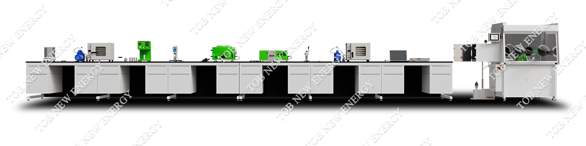
Coin cell lab line


I. Low-Budget Laboratory Setup

Positioning: Fundamental research and feasibility validation

 1. Core Infrastructure (All Cell Types)

Equipment

Function

Engineering Advantages

Typical Applications

Manual Glove Box

Provides inert atmosphere (≤1 ppm H₂O/O₂)

Prevents material degradation and parasitic reactions

Electrode handling, slurry prep, cell assembly

Analytical Balance (0.1 mg)

Precise mass measurement

Ensures accurate electrode loading

Material formulation, electrolyte dosing

Vacuum Drying Oven

Removes residual moisture

Improves electrochemical stability

Electrode, separator, material drying

Laboratory Fume Hood

Solvent vapor extraction

Enhances operator safety

Slurry preparation, electrolyte handling

Deionized Water System

Supplies high-purity water

Prevents ionic contamination

Cleaning, material processing


2. Coin Cell Laboratory (CR20xx)

Equipment

Function

Advantages

Engineering Use

Manual Coin Cell Crimper

Seals coin cells mechanically

Simple, reliable, low cost

Material screening, baseline electrochemistry

Disc Cutter

Cuts electrodes/separators

Uniform geometry, reduced variability

Reproducible coin cell assembly

Manual Slurry Mixer

Mixes active materials and binders

Flexible formulation testing

Cathode/anode development

Manual Coating Applicator

Applies slurry to foil

Fast iteration, adjustable thickness

Small-batch electrode trials

Compact Roll Press

Densifies electrodes

Improves conductivity and adhesion

Capacity and cycle optimization


3. Cylindrical Cell (18650 / 21700 – Feasibility Level)

Equipment

Function

Advantages

Engineering Use

Manual Slitting Machine

Cuts electrode sheets into strips

Low investment, format flexibility

Small-batch cylindrical trials

Manual Winding Jig

Winds electrodes into cylindrical form

Enables geometry validation

Early cylindrical feasibility

Spot Welding Machine

Connects tabs and leads

Stable electrical connection

Internal resistance control

Manual Electrolyte Filling

Injects electrolyte

Supports chemistry variation

Wetting behavior studies

Small Aging Cabinet

Stores cells under control

Enables initial formation

Short-term stability evaluation


4. Pouch Cell (Single-layer)

Equipment

Function

Advantages

Engineering Use

Manual Stacking Fixture

Aligns electrodes/separators

Improves layer consistency

Prototype pouch validation

Vacuum Sealing Machine

Seals pouch under vacuum

Prevents air/moisture ingress

Leak prevention

Electrolyte Injection Tool

Fills electrolyte accurately

Avoids over/under-filling

Electrochemical consistency


II. Mid-Budget Laboratory Setup

Positioning: Process optimization and pilot validation

1. Infrastructure Upgrade

Equipment

Function

Engineering Advantages

Application

Automatic Glove Box (Dual Station)

Parallel inert processing

Improved efficiency, workflow separation

Medium-throughput R&D

Vacuum Planetary Mixer

Uniform slurry mixing + degassing

Reduces coating defects

Process optimization

Continuous Coating & Drying Unit

Continuous electrode fabrication

Stable thickness and porosity

Scale-up evaluation

Automatic Roll Press

Uniform densification

Reduces batch variability

Performance consistency

Precision Slitter

High-accuracy electrode cutting

Supports multiple formats

Cylindrical & pouch cells


2. Coin Cell (High-Throughput)

Equipment

Function

Advantages

Engineering Role

Automatic Coin Cell Assembler

Automated stacking & crimping

High repeatability

Statistical material screening

Electrolyte Dispensing System

Precise volume control

Reduces operator error

Comparative testing

Barcode Tracking

Sample identification

Full traceability

Data integrity


3. Cylindrical Cell (18650 / 21700 / 32140)

Equipment

Function

Advantages

Engineering Role

Semi-Automatic Winder

Controlled electrode winding

Lower defect rate

Yield evaluation

Laser / Ultrasonic Welding

High-quality tab welding

Stable electrical paths

Resistance control

Controlled Filling System

Accurate electrolyte injection

Improved wetting

Cycle life optimization

Formation & Grading Cabinets

Initial cycling & sorting

Quality differentiation

Process window definition


4. Pouch Cell (Multi-layer)

Equipment

Function

Advantages

Engineering Role

Semi-Automatic Stacker

Multi-layer electrode stacking

Alignment accuracy

Layer consistency

Vacuum Heat Sealer

Multi-edge sealing

Repeatable sealing quality

Reliability improvement

Degassing Station

Removes trapped gas

Enhances cycle life

Long-term stability


III. High-Budget Laboratory / Pilot Facility

Positioning: Direct production transfer


1. Production-Grade Infrastructure

Equipment

Function

Engineering Advantages

Application

Central Slurry System

Large-batch mixing

High uniformity

Pilot-scale coating

Automatic Coating Line

Precision coating

Production-level consistency

Scale validation

Solvent Recovery System

Solvent recycling

Cost and environmental control

Sustainable operation

Roll-to-Roll Calender

Continuous densification

Industrial electrode quality

Manufacturing transfer

MES Data System

Process monitoring

Traceability & optimization

Factory readiness


2. Cylindrical Cell (Pilot Level)

Equipment

Function

Advantages

Engineering Role

High-Speed Winding Machine

Automated winding

High throughput

Production simulation

Inline Welding & Inspection

Real-time defect detection

Yield protection

Quality assurance

Vacuum Filling & Soaking

Improved wetting

Shorter formation

Process efficiency

Automated Formation & Aging

Capacity grading

Consistent quality

Production readiness


3. Pouch Cell Pilot Line

Equipment

Function

Advantages

Engineering Role

Automatic Stacking / Z-Folding

High-precision stacking

Layer repeatability

Pilot production

Inline Sealing Line

Automated pouch forming

Low leakage rate

Reliability validation

Automated Degassing

Gas removal

Safety and lifespan

Quality control

Formation & Aging Warehouse

Large-scale formation

Production simulation

Capacity consistency


4. Advanced Safety & Analysis

Equipment

Function

Engineering Value

Application

High-Power Cyclers

High-current testing

Power capability validation

EV & ESS cells

Abuse Test Chambers

Safety testing

Failure mechanism analysis

Certification prep

CT Scanning System

Internal defect imaging

Root cause analysis

Design optimization


Conclusion

A lithium battery laboratory in 2026 must be designed as a scalable engineering system, not a collection of isolated tools.

From low-budget research labs to pilot-scale facilities, each equipment decision should serve a clear engineering purpose: enabling reliable data, reducing scale-up risk, and accelerating the transition to production.

At TOB NEW ENERGY, laboratory systems are engineered as the first controllable stage of manufacturing, ensuring that innovation can move efficiently from concept to commercialization.


Lithium-Ion Battery Manufacturing Process Step-by-Step Guide

Lithium-ion battery manufacturing is a multidisciplinary engineering process that integrates electrochemistry, materials science, precision machinery, thermal engineering, automation control, and factory-level system design. Although the basic working principle of lithium-ion batteries is well known, the industrial realization of stable, high-yield, and high-performance cell production requires far more than simply following a laboratory recipe. In real manufacturing environments, product consistency depends on the interaction between process parameters, equipment accuracy, environmental control, and line integration. Even small deviations in coating thickness, slurry viscosity, electrode density, or moisture level can result in significant differences in capacity, internal resistance, safety performance, and cycle life.

For this reason, companies planning to enter battery manufacturing must understand the complete production workflow before purchasing equipment or designing a factory. In large projects, the manufacturing process cannot be treated as a series of independent machines. Instead, it must be designed as a continuous engineering system covering electrode preparation, cell assembly, electrolyte filling, formation, aging, and testing. Professional planning of the production line, utility systems, and cleanroom environment is essential to avoid costly redesign later. In practical projects, many failures occur not because of material chemistry, but because the manufacturing process was not properly engineered from the beginning.

As a one-stop provider of battery equipment and factory solutions, TOB NEW ENERGY lithium-ion battery production line solutions are developed to support the complete life-cycle from laboratory research to pilot scale and full mass production, ensuring that equipment compatibility, process scalability, and future expansion are considered during the initial design stage.

This article provides a detailed engineering-level explanation of the lithium-ion battery manufacturing process, focusing on real industrial workflow rather than simplified laboratory descriptions.
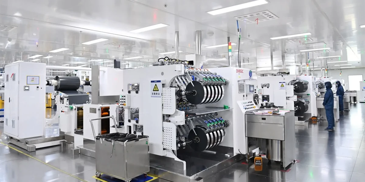
TOB NEW ENERGY lithium-ion battery production line solutions


1. Overall Structure of Lithium-Ion Battery Manufacturing

Although different cell formats such as cylindrical, pouch, and prismatic require different assembly methods, the overall production flow of lithium-ion batteries follows a similar structure. The entire manufacturing system can be divided into three major stages: electrode preparation, cell assembly, and electrochemical activation with testing. Each stage contains multiple processes that must be precisely controlled to ensure final product quality.

Manufacturing Stage

Main Processes

Engineering Purpose

Electrode Preparation

Mixing, coating, drying, calendering, slitting

Produce uniform cathode and anode

Cell Assembly

Stacking or winding, welding, packaging, electrolyte filling, sealing

Build mechanical structure

Formation & Testing

Formation, aging, grading, electrical testing

Activate and classify cells

Factory Integration

Cleanroom, utility system, automation, MES

Ensure stable production

In industrial projects, these stages must be designed together rather than separately. A well-engineered production line requires correct matching of machine capacity, material flow, drying length, cleanroom level, and power supply capability. For this reason, professional battery factory layout and line design solutions are usually required before equipment procurement begins.


2. Electrode Preparation: Foundation of Battery Performance

Electrode preparation is the most critical part of lithium-ion battery manufacturing because the microstructure formed during this stage directly determines energy density, cycle life, internal resistance, and safety characteristics. Once electrodes are produced, most performance parameters cannot be corrected in later steps, which is why industrial factories invest heavily in high-precision coating and calendering systems.


2.1 Slurry Mixing Engineering

The first step is preparing cathode and anode slurry by mixing active materials, conductive additives, binder, and solvent. In laboratory scale, mixing may appear simple, but in industrial production the slurry must maintain stable viscosity, uniform particle distribution, and repeatable rheological behavior over long production runs. Variations in dispersion quality will lead to coating defects, uneven thickness, and capacity variation between cells.

Parameter

Typical Industrial Requirement

Mixing uniformity

±1% solid distribution

Vacuum level

<−0.09 MPa

Temperature control

±2 °C

Viscosity deviation

< 3%

Batch repeatability

< 2%

Modern production lines use vacuum planetary mixers or double-planetary mixers with precise temperature and speed control. For research institutes and pilot plants, flexible parameter adjustment is essential, which is why battery slurry mixing equipment for R&D applications must support multiple material systems and small batch sizes.

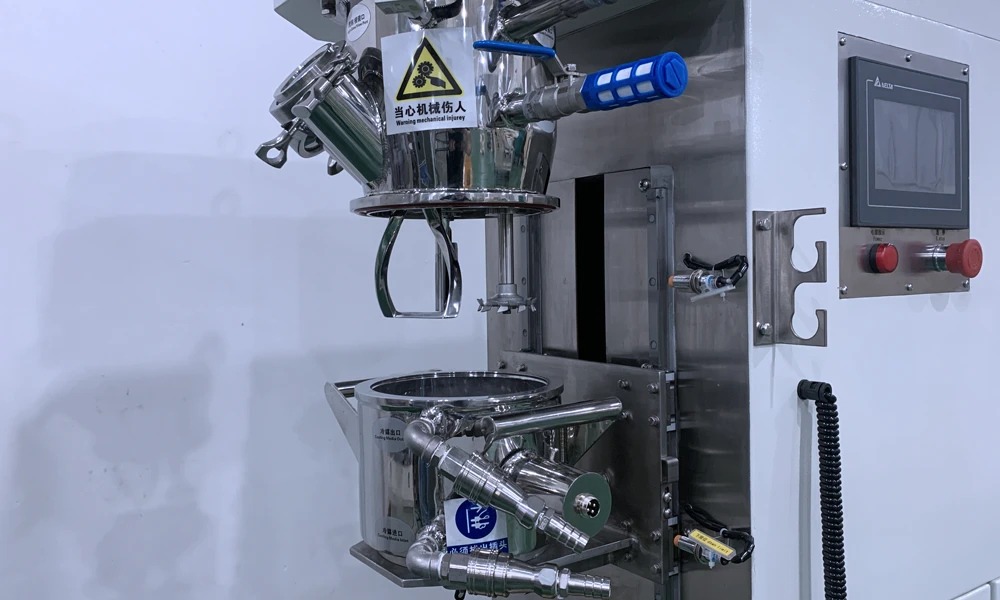
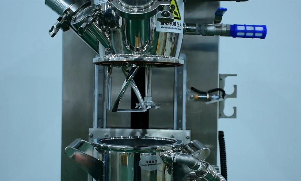
Battery Slurry Mixer

2.2 Precision Coating Process

After mixing, the slurry is coated onto current collectors. The coating process must control thickness, weight, and uniformity across the entire width of the electrode. Even slight thickness variation may cause capacity imbalance during formation. Industrial lines usually use slot-die coating technology because it allows continuous production with high precision and low material waste, while doctor-blade coating is still widely used in laboratory and pilot environments due to its flexibility.

Coating Method

Precision

Typical Application

Slot die coating

High

Mass production

Doctor blade coating

Medium

Lab / pilot line

Comma coating

Medium

Special materials

In high-capacity factories, coating machines are often integrated with multi-zone drying ovens to maintain continuous production without interrupting material flow.


2.3 Drying and Solvent Removal

The drying process removes solvent from the coated electrode while preserving the designed microstructure. This step requires careful control of temperature gradient, air flow speed, and solvent recovery system. If drying is too fast, cracks may form in the coating layer. If drying is insufficient, residual solvent may remain, leading to gas generation during formation.

Industrial coating lines usually include long convection ovens with multiple heating zones. In addition to temperature control, modern factories must also consider energy efficiency and solvent recycling to reduce operating cost.


2.4 Calendering and Density Control

Calendering compresses the dried electrode to achieve the target density and porosity. Higher density increases energy density, but excessive compression reduces ionic transport and may shorten cycle life. Therefore, calendering parameters must be optimized according to the material system and cell design.

Calendering Parameter

Influence on Cell

Pressure

Density and capacity

Temperature

Adhesion strength

Roller gap

Thickness uniformity

Speed

Surface quality

Pilot lines often require adjustable roll pressure and temperature to support different research projects, which is why scalable equipment design is important when building a battery pilot line.


2.5 Slitting and Dust Control

After calendering, the wide electrode roll is cut into narrow strips. This process must avoid burrs and particles because metal dust can cause internal short circuits. Industrial slitting machines include tension control systems, edge trimming, and dust collection units to maintain clean electrode surfaces.


3. Cell Assembly: Mechanical Structure Formation

Once electrodes are prepared, the next stage is assembling the cell structure. The assembly method depends on cell format, but the engineering principles are similar. The process must ensure accurate alignment, clean environment, and reliable electrical connections.

Cell Format

Typical Assembly Method

Cylindrical

Winding

Pouch

Stacking

Prismatic

Stacking or winding

Stacking machines require high positioning accuracy, while winding machines must maintain stable tension to avoid wrinkles. Welding of tabs is another critical step because poor welding increases internal resistance and heat generation during cycling. Industrial production usually uses ultrasonic welding or laser welding depending on tab material and thickness.

Packaging must be performed in cleanroom conditions to prevent dust contamination. Electrolyte filling requires vacuum equipment to ensure complete penetration into the electrode pores. Finally, sealing must guarantee long-term hermeticity to prevent moisture ingress.

Process Area

Typical Cleanroom Level

Coating

ISO 8

Assembly

ISO 7

Electrolyte filling

ISO 6

Proper cleanroom design is part of factory engineering and should be considered together with equipment layout.


4. Formation, Aging, and Testing

Formation is the electrochemical activation process in which the solid electrolyte interface (SEI) is formed on the anode surface. This step requires precise current control and temperature management. It is also one of the most expensive sections of a battery factory because thousands of channels must operate simultaneously for long periods.

Process

Purpose

Formation

Build stable SEI

Aging

Stabilize chemistry

Capacity test

Measure performance

Grading

Sort cells

Formation equipment occupies a large area and requires strong power supply capacity, which must be considered during factory planning. Incorrect estimation of formation capacity is a common mistake in new battery projects.


5. Importance of Production Line Integration

In industrial battery manufacturing, process stability depends not only on individual machines but also on how the entire line is integrated. The coating speed must match the drying length, the slitting speed must match assembly capacity, and formation channels must match daily output. Utility systems such as compressed air, chilled water, vacuum, and power supply must also be designed according to production scale.

For this reason, many companies prefer working with a one-stop battery equipment supplier that can provide process design, equipment manufacturing, installation, and commissioning as a complete package instead of purchasing machines from multiple vendors.


6. From Laboratory Research to Mass Production

Most battery projects start from laboratory research, then move to pilot scale, and finally to mass production. Equipment selection should consider this transition. Laboratory machines should allow parameter flexibility, pilot lines should support small-batch stability, and production lines must focus on automation and yield. Choosing scalable equipment reduces development time and avoids repeated investment.

TOB NEW ENERGY provides complete solutions covering laboratory equipment, pilot lines, and turnkey production lines, allowing customers to maintain consistent process parameters while increasing production capacity.


About TOB NEW ENERGY

TOB NEW ENERGY is a professional supplier of lithium-ion battery equipment and complete production line solutions serving battery manufacturers, universities, research institutes, and new energy companies worldwide. The company provides full support from laboratory research to pilot scale and mass production, including factory layout design, equipment manufacturing, installation, commissioning, and operator training.

With extensive experience in lithium-ion, sodium-ion, solid-state, lithium-sulfur, and dry electrode technologies, TOB NEW ENERGY delivers customized engineering solutions that help customers build reliable, scalable, and future-ready battery manufacturing facilities.
Main Causes of Pouch Cell Sealing Leakage

Pouch cell batteries are widely used in consumer electronics, electric vehicles, and energy storage systems because of their high energy density, lightweight structure, and flexible design. Compared with cylindrical and prismatic cells, pouch cells use laminated aluminum laminated film as the outer packaging instead of a rigid metal case. This structure allows better space utilization and lower weight, but it also makes the sealing process much more critical. Any defect in the sealing area may lead to electrolyte leakage, moisture ingress, gas escape, or internal contamination, which can seriously affect battery performance, safety, and cycle life. For this reason, sealing quality control is one of the most important steps in pouch cell manufacturing.

Sealing leakage in pouch cells is rarely caused by a single factor. In most cases, it is the result of interactions between process parameters, material properties, equipment condition, and environmental factors. Even when each parameter appears to be within specification, small deviations can combine to create weak sealing interfaces or microscopic leakage paths. From an engineering perspective, leakage causes can be broadly categorized into three groups: process-related issues, material-related defects, and contamination or handling problems. Understanding how these factors affect the sealing interface is essential for identifying root causes and implementing effective countermeasures.

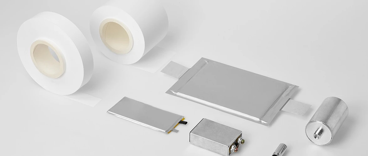
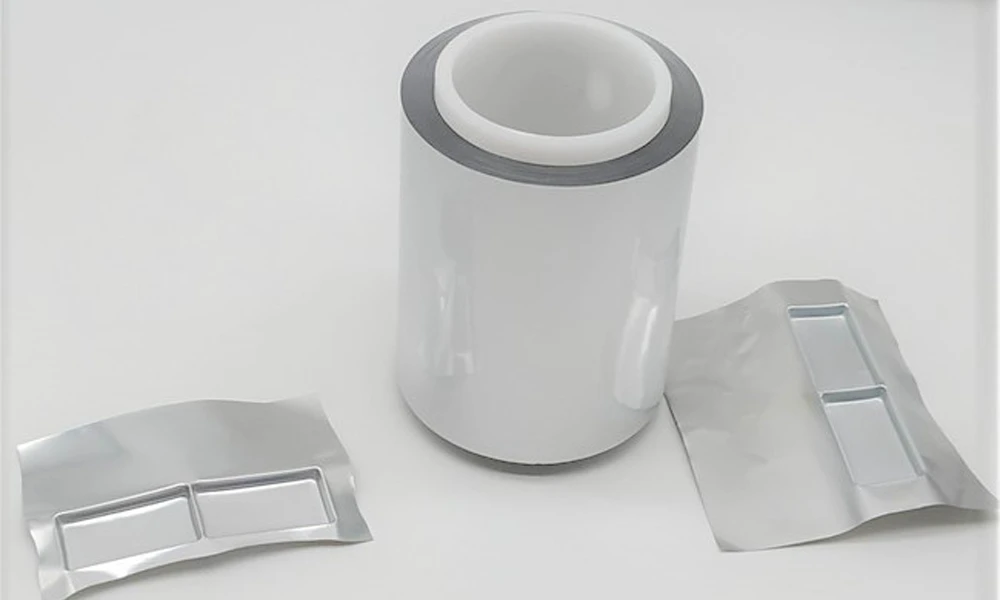
Aluminum laminated film

1. Process-Related Causes

The heat sealing process is highly sensitive to temperature, pressure, and time. These three parameters determine whether the inner polymer layer of the pouch film can fully melt, flow, and bond into a continuous interface. If any of these parameters are not properly controlled, sealing defects can occur.
One common issue is insufficient sealing temperature. When the temperature is too low, the inner sealing layer does not melt completely, resulting in weak bonding and poor adhesion. Although the seal may appear intact visually, the interface may contain micro-voids that can later develop into leakage paths. Conversely, excessive temperature can degrade the polymer or damage the adhesive layer between the aluminum foil and the outer film, reducing mechanical strength and causing delamination over time.
Pressure is equally important. Insufficient pressure prevents the molten polymer from fully contacting and filling surface irregularities, while excessive pressure can squeeze out the molten layer, reduce sealing thickness, or even damage the aluminum layer. Uneven pressure distribution across the sealing area can create regions of inconsistent bonding strength, which are particularly prone to leakage under mechanical stress.
Sealing time also plays a critical role. If the dwell time is too short, the polymer may not have enough time to flow and bond properly. If it is too long, overheating or material deformation may occur. In high-speed production lines, maintaining consistent sealing time across all cells becomes more challenging, increasing the risk of variability in seal quality.

2. Material-Related Causes

The quality and consistency of the aluminum laminated film directly affect sealing performance. Variations in film thickness, coating uniformity, or adhesive bonding between layers can lead to inconsistent sealing behavior. For example, if the inner sealing layer has uneven thickness, some areas may melt and bond properly while others remain under-sealed.
Defects in the film, such as pinholes, scratches, or micro-cracks, can also create leakage paths. These defects may originate during film manufacturing, transportation, or handling. Even if the sealing process is well controlled, a defective film cannot provide reliable barrier performance.
Material compatibility is another important factor. The sealing behavior depends on the melting characteristics of the inner polymer layer. If different batches of film have slightly different melting temperatures or compositions, the same sealing parameters may not produce consistent results. This is particularly critical in large-scale production, where small variations in material properties can lead to significant differences in yield.
Electrode and tab materials can also influence sealing quality. The presence of metal tabs in the sealing area introduces discontinuities in the interface. If the sealing parameters are not optimized for these regions, gaps or weak bonding may occur around the tabs, making them a common source of leakage.

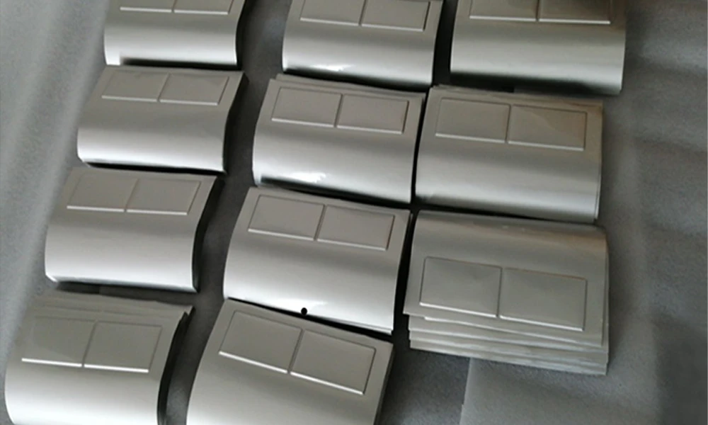
Aluminum laminated film

3. Contamination and Handling Issues

Contamination in the sealing area is one of the most frequent causes of leakage in real production environments. Substances such as electrolyte residue, dust particles, or electrode debris can prevent proper bonding between the polymer layers. Even a small amount of contamination can create a micro-channel that allows gas or liquid to pass through the seal.
Electrolyte contamination is particularly problematic. During filling and handling, small amounts of electrolyte may spread to the sealing area. Because electrolyte components can interfere with polymer bonding, their presence can significantly reduce sealing strength. In some cases, the seal may initially appear acceptable but fail during storage or cycling due to chemical interaction at the interface.
Improper handling can also damage the pouch film before sealing. Scratches, folds, or mechanical deformation can weaken the film structure, making it more susceptible to leakage. Misalignment during sealing may result in uneven pressure distribution or incomplete sealing width, further increasing the risk of defects.

4. Equipment and Tooling Factors

The condition and design of sealing equipment also play a significant role. Worn or contaminated sealing heads can lead to uneven temperature distribution or inconsistent pressure. If the heating element does not maintain a stable temperature across the entire sealing width, some areas may be under-sealed while others are overheated.
Tooling alignment is another critical factor. Misaligned sealing jaws can create uneven pressure distribution, leading to weak bonding in certain regions. In addition, insufficient control of cooling after sealing can affect the crystallization and solidification of the polymer layer, influencing final seal strength.

5. Summary of Leakage Causes

The main causes of pouch cell sealing leakage can be summarized as follows:

  • Improper heat sealing parameters (temperature, pressure, time)
  • Variations or defects in aluminum laminated film
  • Contamination in the sealing area (electrolyte, dust, particles)
  • Mechanical damage or misalignment during handling
  • Equipment instability or poor maintenance

In practice, leakage is often the result of multiple factors acting together rather than a single isolated issue. For example, a slightly low sealing temperature combined with minor contamination may be enough to create a leakage path that would not occur if either factor were controlled independently.


About TOB NEW ENERGY

TOB NEW ENERGY is a leading provider of one-stop battery manufacturing solutions, covering pouch cell lab lines, pilot lines, and pouch cell production lines. Our services include customized battery equipment supply, process optimization, battery material support, and technical training for battery engineers and R&D teams worldwide.

NFPP Sodium-Ion Battery Material A High-Safety, Low-Cost Cathode

As the global battery industry seeks alternatives to lithium-based chemistries, sodium-ion batteries have steadily moved from academic research into early-stage commercialization. Among various cathode candidates, NFPP (Na₃Fe₂(PO₄)₃) has gained increasing attention due to its balanced performance, structural stability, and supply-chain advantages. Rather than pursuing extreme energy density, NFPP represents a pragmatic materials strategy aimed at cost control, safety, and long service life.

This article explores NFPP from a materials and manufacturing perspective, examining why it is considered one of the most realistic cathode options for near-term sodium-ion battery deployment.

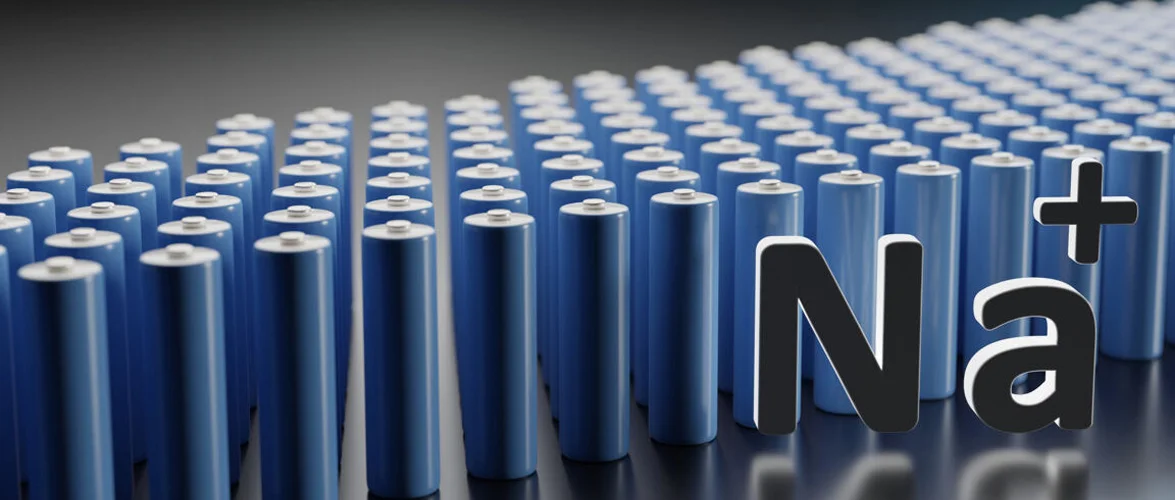
NFPP Sodium-Ion Battery Material

01. Why NFPP Matters in Sodium-Ion Battery Development

Sodium-ion batteries differ fundamentally from lithium-ion systems in ionic radius, diffusion kinetics, and electrode–electrolyte compatibility. These differences impose stricter requirements on cathode structure and chemical stability.

NFPP belongs to the NASICON-type phosphate framework, a structure known for its three-dimensional sodium-ion diffusion channels. This framework provides:

● Stable crystal structure during repeated Na⁺insertion and extraction

● Moderate operating voltage around 3.0–3.2 V vs. Na/Na⁺

● Good thermal and chemical stability compared with layered oxides

From an industrial perspective, NFPP does not rely on nickel, cobalt, or other high-cost metals. Iron and phosphate-based chemistries offer predictable pricing and lower geopolitical risk, which aligns well with large-scale stationary energy storage and low-cost mobility applications.


02. Structural Characteristics: NASICON Framework as a Stability Anchor

The electrochemical behavior of NFPP is closely linked to its crystal structure. The NASICON framework consists of rigid PO₄tetrahedra and FeO₆octahedra, forming interconnected channels for sodium-ion transport.

Key structural advantages include:

● Low volume change during cycling, reducing mechanical stress

● Stable Fe³⁺/Fe²⁺redox couple with limited side reactions

● Inherent resistance to oxygen release at elevated temperatures

While NFPP does not match layered oxide cathodes in theoretical energy density, its structural robustness translates into long cycle life, especially under high-temperature or high-rate operating conditions.


03. Electrochemical Performance: Trade-Offs That Favor Reliability

In practical sodium-ion cells, NFPP typically delivers:

● Specific capacity in the range of 110–120 mAh/g

● Excellent capacity retention over extended cycling

● Stable performance under moderate to high C-rates

The relatively flat voltage plateau simplifies battery management system (BMS) design and improves state-of-charge estimation accuracy. For applications where predictability and durability outweigh peak energy density, NFPP offers a compelling balance.

It is worth noting that ongoing research focuses on particle size control, carbon coating, and dopant modification to further enhance rate capability and electronic conductivity.


04. Manufacturing Compatibility: Designed for Process Stability

One often-overlooked advantage of NFPP is its process friendliness. Compared with moisture-sensitive layered oxides, phosphate-based materials demonstrate higher tolerance to ambient processing conditions.

From electrode manufacturing to cell assembly, NFPP shows:

● Good compatibility with conventional slurry-based coating processes

● Potential adaptability to emerging dry electrode technologies

● Stable behavior during calendaring and electrode densification

These characteristics reduce manufacturing risk when scaling from laboratory cells to pilot and mass production lines.


05. Application Scenarios: Where NFPP Fits Best

NFPP is not positioned as a universal replacement for lithium-ion cathodes. Instead, it targets specific scenarios where sodium-ion technology offers system-level advantages:

● Grid-scale and distributed energy storage systems

● Low-speed electric vehicles and two-/three-wheel mobility

● Backup power and industrial energy storage solutions

In these applications, cost per cycle, safety margin, and supply stability often outweigh volumetric energy density.


06. From Materials to Manufacturing: An Integrated Perspective

Successful deployment of NFPP-based sodium-ion batteries depends not only on material performance but also on the integration of equipment, process control, and quality assurance.

Companies such as TOB NEW ENERGY support this transition by providing integrated solutions covering material preparation, electrode processing, and complete sodium-ion battery production lines. By aligning material characteristics with manufacturing capabilities, NFPP-based systems can move more efficiently from development to commercialization.


Conclusion

NFPP is not a breakthrough material defined by extremes. Instead, it represents a well-engineered compromise—offering stability, safety, and economic feasibility in a rapidly evolving battery landscape. As sodium-ion batteries continue to mature, NFPP stands out as one of the most industrially realistic cathode materials available today.


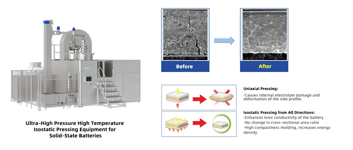
Scaling Solid-State Battery Production High-Pressure 600MPa Warm Isostatic Press (WISP) Solutions

The global race for the next generation of energy storage is centered on Solid-State Batteries (SSBs). While the potential for higher energy density and enhanced safety is clear, the transition from lab-scale prototypes to mass production remains a challenge. One of the most critical hurdles is ensuring perfect interface contact between solid electrolytes and electrodes.

To bridge this gap, we are proud to introduce our high-performance Warm Isostatic Press (WISP), a machine specifically engineered for SSB pilot research and large-scale manufacturing.


Why Isostatic Pressing is Critical for Solid-State Batteries

Unlike traditional liquid lithium-ion batteries, solid-state batteries rely on the seamless contact of solid materials. Any microscopic voids or "air gaps" at the interface increase internal resistance, leading to poor cycle life and reduced power output.


Warm Isostatic Pressing (WIP) applies uniform pressure from all directions using a liquid medium at elevated temperatures. This process:

● Eliminates Voids: Ensures 100% densification of the solid electrolyte layer.

● Enhances Interface Contact: Minimizes interfacial impedance between the cathode, electrolyte, and anode.

● Improves Structural Integrity: Prevents delamination during high-rate charging and discharging.


Engineering Excellence: 600MPa at 150°C

Our latest WISP system is designed to meet the most rigorous industrial requirements. With asteady-state working pressure of 600MPa, it provides the extreme force necessary to densify even the toughest ceramic electrolytes, such as sulfides and oxides.

Coupled with a maximum working temperature of 150°C, the equipment allows for the "softening" of certain battery components during pressing, ensuring a more homogeneous and robust cell structure without damaging sensitive chemical compositions.


Large-Format Capability for Industrial Scaling

One of the standout features of this system is its capacity. It is designed to handle large-cell formats with dimensions up toL: 950mm * W: 270mm * H: 30mm. This makes it one of the few machines on the market capable of supporting the production of large-format automotive-grade solid-state battery cells.


Technical Superiority and Precision Control

Efficiency and precision are the backbones of our design. The system utilizes a dual-media approach:hydraulic oilfor the power system andthermal oilas the working medium. This ensures both safety and high-performance thermal conductivity.

● Rapid Pressurization:Reaching 600MPa in under 5 minutes, significantly reducing cycle times and increasing throughput.

● Thermal Stability:With a temperature deviation of only ±3°C, your battery materials undergo uniform heat treatment, ensuring batch-to-batch consistency.

● Pressure Precision:Maintaining stability within ±2% during the hold time is vital for delicate electrolyte layers that are prone to cracking under fluctuating loads.

Warm Isostatic Press (WISP)


Technical Specifications at a Glance

Item

Parameters

Remarks

Chamber Diameter

Φ300mm

Effective Depth

1000mm

Max Design Pressure

660MPa

Max Working Pressure

600MPa

Max Working Temperature

150°C

Max Temp. Deviation

±3°C

Measured in medium under steady state

Hydraulic Power Medium

Hydraulic Oil

Pressure Flow Rate

≥3L/min

Pressure Stability

Within ±2%

During steady state

Pressurization Time

≤5min

0 to 600MPa

Working Medium

Thermal Oil


Ready for the Future of Battery Manufacturing

Whether you are in the R&D phase optimizing electrolyte formulations or moving into mass production for the electric vehicle market, our Warm Isostatic Press is the "missing link" in your production line.

By combining extreme pressure, precise temperature control, and a large processing volume, this equipment is the essential tool for any organization serious about leading the solid-state battery revolution.


Contact Our Experts

Ready to elevate your solid-state battery production? Our engineering team is available to discuss how our 600MPa WISP can integrate into your existing workflow.

Contact Us Today for a Quote or Technical Consultation

How Modern Scrap Metal Balers Help Recycling Plants Meet 2026 Environmental Standards

Modern scrap metal balers help recycling facilities meet strict 2026 environmental standards by incorporating highly sealed hydraulic systems to prevent soil contamination, utilizing energy-efficient servo motors to reduce carbon footprints, and enabling extreme-density compaction that drastically cuts transportation emissions.

The New Era of Green Recycling Compliance As we progress through 2026, the global scrap metal recycling industry is facing unprecedented regulatory scrutiny. Governments and environmental protection agencies across Europe, North America, and rapidly developing manufacturing hubs are strictly enforcing new Environmental, Social, and Governance (ESG) mandates. Today, recycling plants are no longer judged solely on the sheer volume of metal they process, but heavily on how sustainably, cleanly, and safely they operate. Upgrading to modern, eco-friendly equipment is no longer just a public relations strategy; it is a strict compliance necessity to avoid heavy fines, operational delays, or facility closures.

Eliminating Soil and Groundwater Contamination Historically, heavy machinery operating in outdoor scrap yards was notorious for severe hydraulic oil leaks. Under the new 2026 international environmental guidelines, even minor soil and groundwater contamination can result in crippling financial penalties. Upgrading your facility with a modern scrap metal baler effectively eliminates this risk. The latest generation of machines is engineered with advanced, leak-free hydraulic architectures. They feature reinforced high-pressure hoses, custom O-ring face seals, and integrated fluid drip trays. These enclosed, fail-safe systems ensure that toxic hydraulic fluids never touch the earth, keeping your daily operations fully compliant.

Reducing the Carbon Footprint of Metal Processing Energy consumption is another major focal point of modern environmental standards. Older, legacy balers that run continuously draw massive amounts of electricity from the grid, contributing heavily to a recycling facility's overall carbon footprint. Today’s state-of-the-art eco-friendly baling equipment utilizes highly intelligent PLC (Programmable Logic Controller) systems combined with Variable Frequency Drives (VFDs) and servo motors. This smart technology ensures the machine's hydraulic pumps only consume peak power during the actual compaction stroke, and immediately power down during idle times. This drastically lowers the overall kilowatt-hours (kWh) used per ton of processed scrap.

Slashing Scope 3 Emissions in the Supply Chain Perhaps one of the most significant environmental benefits of a high-performance hydraulic metal baler machine occurs entirely outside the scrap yard boundaries. Shipping loose, uncompacted scrap requires an excessive number of diesel truck trips to transport the material to the smelter. By compacting loose metal into ultra-dense, uniform blocks, modern balers maximize the legal weight payload of every single outbound truck. This significantly reduces the total number of heavy-duty vehicles on the road, directly and measurably cutting the greenhouse gas (Scope 3) emissions associated with your supply chain logistics.

Future-Proofing Your Recycling Business Ultimately, meeting 2026 environmental standards is about future-proofing your business. Regulatory pressures will only increase in the coming years. By proactively investing in advanced compaction technology, scrap yard operators can ensure uninterrupted operations, qualify for green industry incentives, and build stronger relationships with top-tier steel mills that require sustainable supply chains.

Exploring the 5-Axis CNC Bridge Saw Machine Features & Benefits

In the world of stone cutting, the 5 - Axis CNC Bridge Saw Machine is a game - changer. If you're in the market for a top - notch cutting solution, you've likely come across terms like 5 Axis Bridge Saw, Marble Bridge Saw, or Stone Bridge Saw, all of which are closely related to this remarkable machine.


How Does it Fare with Different Stone Hardness?

One common concern for buyers is how well the 5 - Axis CNC Bridge Saw Machine handles various stones. Whether it's the hardness of granite or the elegance of marble, this machine is designed to excel. Its high - quality diamond - tipped blades, combined with precise control from the five - axis system, can effortlessly cut through both hard and soft stones. For instance, when cutting granite, the machine's robust power and accurate axis movements ensure clean, smooth cuts without chipping. And for marble, it can achieve intricate designs with the required finesse.


Customization and Design Flexibility

Many customers worry about the machine's ability to bring their design ideas to life. The 5 - Axis CNC Bridge Saw Machine addresses this with ease. You can create stone drawings directly on the machine's computer or upload CAD drawings via USB. The system then provides a simulation demo, allowing you to visualize the final product. This means you can make adjustments and ensure your design is perfect before starting the cutting process.


Maintenance and Long - Term Costs

Another pain point for potential buyers is maintenance and long - term costs. While the 5 - Axis CNC Bridge Saw Machine is an investment, regular maintenance, such as cleaning, lubrication, and blade sharpening, is straightforward. Our team of experts is always available to provide guidance on proper maintenance procedures. This ensures the machine runs smoothly for years, reducing the overall cost of ownership.


Case in Point

A company that makes stone things was having a time making complicated marble sculptures. They bought our 5 Axis CNC Bridge Saw Machine and it made a difference. They could make detailed designs that were very precise which helped them get more clients.

So if you are looking for a 5 Axis Bridge Saw or a Marble Bridge Saw or a Stone Bridge Saw our 5 Axis CNC Bridge Saw Machine is what you need. It is very good at making cuts and it is flexible and lasts a long time. You can visit our product page to learn more about the 5 Axis CNC Bridge Saw Machine. Start making your stone cutting projects better.


Maximize Shine with High - Performance Stone Polishing Machines

Hey everyone! If you're in the stone industry, you know how crucial it is to get that perfect shine on your stone surfaces. That's where high - performance Stone Polishing Machines come in.


The Many Facets of Stone Polishing Machines


Surface Restoration

One of the primary jobs of a Stone Polishing Machine is to get rid of that pesky surface damage. You know, those saw marks, scratches, and general wear and tear that can make a beautiful piece of stone look less than its best. With a two - stage process of rough and fine polishing, Stone polishing machines can rejuvenate the luster of stones, endowing them with exquisitely smooth surfaces.


Achieving that Mirror - like Finish

The real star of the show, though, is the ability of these machines to boost the stone's shine to an incredible level. Using a combination of fine - particle abrasion and a bit of physical - chemical know - how, they can get the surface to a high gloss, often above 85 degrees. It's that mirror - like finish that makes your granite countertops or marble floors really stand out.


Revitalizing and Maintaining Stone

Stone Polishing Machines are also lifesavers when it comes to stone renovation and upkeep. Whether it's the high - traffic floors of a hotel or the walls in a residential home, these machines can handle all kinds of stone, from granite to artificial stone. They tackle issues like stains, aging, and loss of shine, leaving the surface looking as good as new.


Specialized and Versatile Processing

Some models, like tile polishers and edge - rounding machines, are great for those special touches. They can grind edges, create 45° or 30° chamfers, add non - slip grooves, and do arc - shaped polishing. This is perfect for things like stair steps, baseboards, and decorative tiles. And it's not just about natural stones. These machines can also work wonders on epoxy floors, cement floors, and terrazzo, making them super versatile.


A Wide Range of Applicable Materials

These machines aren't picky eaters. They can handle natural stones like marble, granite, limestone, and sandstone, as well as artificial ones such as artificial marble, quartzite, and engineered quartz. Even polished tiles and various types of floors can be precisely polished.


Diverse Application Scenarios

In stone processing plants, these machines are used for tasks like slab thickness adjustment, full - scale polishing, and edge finishing. In construction and decoration projects, they're the go - to for floor and wall renovation, as well as creating those intricate, custom - shaped edges. And in commercial spaces like hotels, malls, and airports, they're essential for maintaining the shine and beauty of the stone surfaces.


If you're looking to take your stone projects to the next level, our Stone Polishing Machines are the answer.They're designed to meet all your granite and marble polishing needs, whether you're using them as a Granite Polishing Equipment or a Marble Grinder and Polisher. Don't miss out on the opportunity to maximize the shine of your stones.

Stone Polishing Machines Transforming Rough Stones into Shiny Masterpieces

In the stone processing industry, stone polishing machine are absolute game - changers. By combining physical abrasion with chemical reactions, stone polisher enhance the gloss and smoothness of stone surfaces, a five-step process comprising ‘coarse grinding → semi-fine grinding → fine grinding → precision grinding → polishing’ resulting in a sleek and attractive finish.

The Marvels of Stone Polishing Machines

Stone polishing machines come in a wide variety,include manual polishing machine, fully automatic polishing machine and robotic polishing machine etc. Every type has its distinct design, crafted to deal with diverse polishing tasks. If you're a local artisan carefully working on a dainty stone carving, or an industrial pro managing large quantities of stone slabs, these machines are essential for achieving that flawless finish.

Marble Polishing Machine

Discovering Polishing Techniques

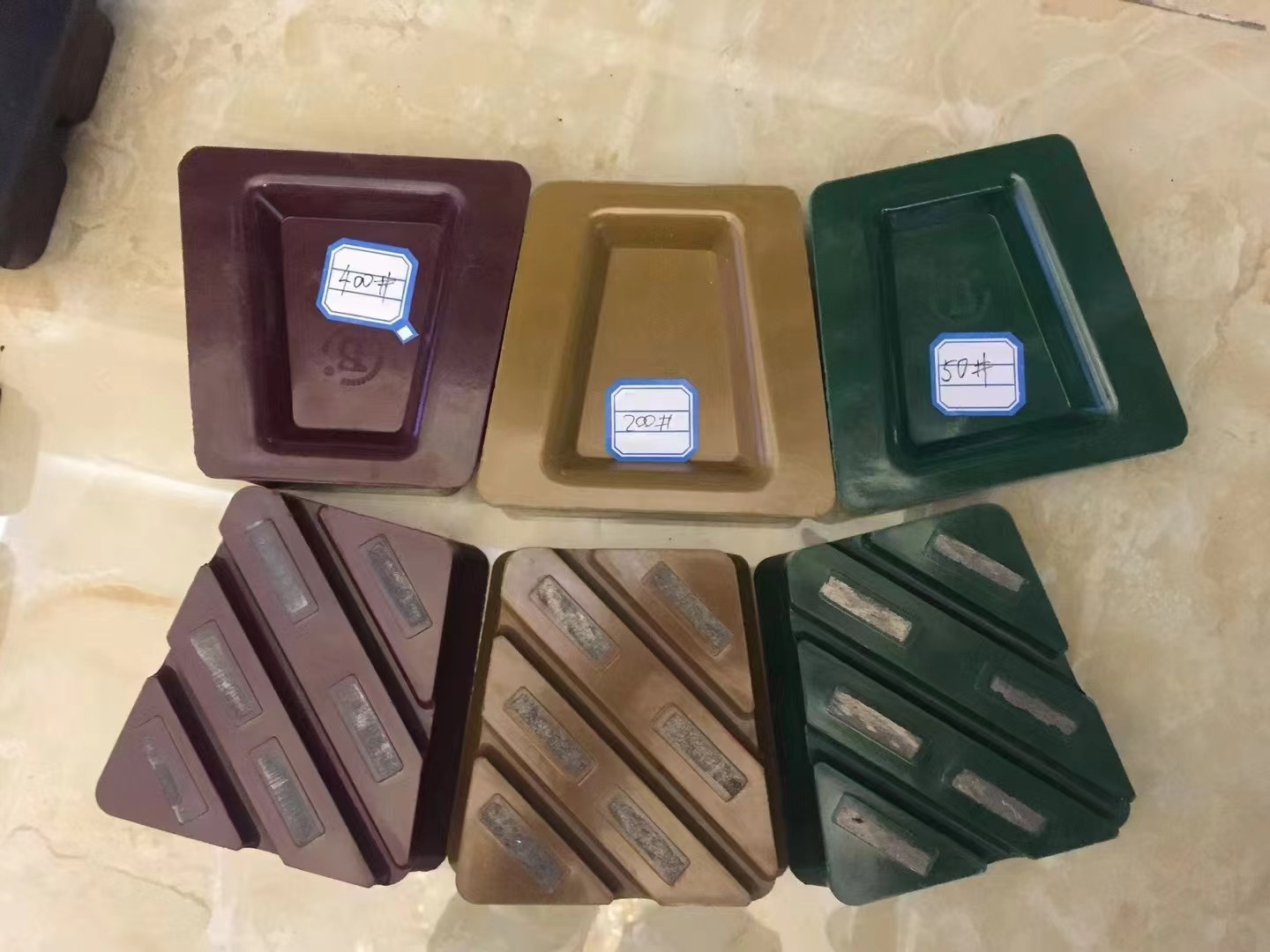
The true allure of stone polishing machines is in the techniques employed. These techniques can make or break the polish. For example, lots of machines use diamond - coated pads. You start with a coarse - grit pad to smooth out any bumps or flaws on the stone's surface. Then, you gradually switch to finer - grit pads. This methodical process is crucial for attaining a sleek, uniform shine. You need to adjust the pressure and speed of these pads according to the stone type. Softer stones require a lighter touch, while harder stones can withstand a bit more force.

Machine Performance: The Heart of the Operation

When it comes to stone polishing, machine performance is super important. A well performing machine can get the job done faster and better, saving you a ton of time and money. High quality motors are the heart of these machines. They give the power needed to polish large stones without breaking a sweat. And then there are those adjustable speed settings. They're like the dials on a control panel, allowing you to fine tune the polishing process based on what you're working on.

Diverse Polishing Applications

Stone polishing machines have a wide range of applications. Stone polishing is primarily used to treat the surfaces of rough-cut slabs or shaped products following the processing of raw blocks, in order to achieve a glossy finish.They are frequently used for treating floor tiles, worktops and wall panels. Once polished, stone not only looks attractive but also becomes more durable and easier to maintain. Many artists also rely on these machines to bring out the beauty of stone carvings.

Maintaining Stone Polishing Quality

The quality of the stone polishing is what it's all about. To keep that quality high, you've got to take good care of the machine. Regular maintenance is key. Check the polishing pads often and replace them when they start to wear out. Lubricate the moving parts so everything runs smoothly. And don't forget to calibrate the sensors. All these little things add up to ensure that every stone you polish comes out looking its absolute best.

In a nutshell, if you're in the market for top - notch stone polishing machines that are great at techniques, performance, applications, and quality, click here to check out our Automatic  Stone Polishing Machine. Our machines are made to meet all your stone polishing needs, turning rough stones into shiny showstoppers every single time.